About to consider placement of bus bars:
I know the thread is old, but the previous advice was much about regulation (thank you everyone!), however I'm fairly sure each 500 card has their own individual reg on their respective PCB's, and the main PSU's are as well supplying the regulated constant voltages (power ratings for PSU's are roughly twice the wattage requirements of all the console pcb's).
But if you don't mind, I'd appreciate some final advice or warning from anyone on the idea below:
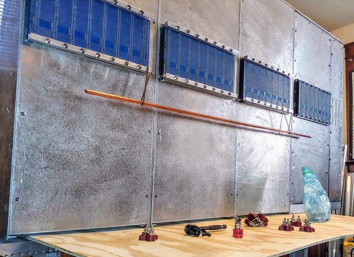
This console frame underside area will be capped with a big metal 'distribution cage' that covers up all bus bars, so shorts/blowouts should not be a problem (not seen in pict, have yet to make).
A single AGND bar is the only one that makes real sense, however I have 4 extra bars, some a little smaller.... so...
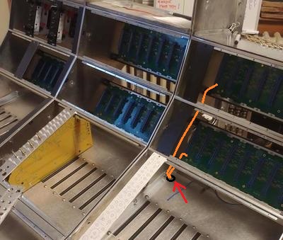
I'm considering how wise it would be to use them to pass +/- 16 down the line of buckets to each channel backplanes (as seen in picture) but then also distribute
into each bucket by drilling holes in underside of frame to bring power up through the bottom into the inside of each bucket to 500 series backplanes, taking care to make runs short and vertical (see below pict with orange power wires 'drawn in').
The inspiration (perhaps a foolish "scaling-up" idea) is from PCB layout; traces of power and signal layers should not run parallel to each other, but where they have to cross over, the layout should minimise parallel runs...so... why not also do this with console power and signal distribution in and around the frame?
Audio signal will of course run
horizontal down the frame and to patch panels, etc, but remain inside the buckets, isolated from underside power distribution bars, and orthogonal to power wires going into buckets.
Overkill, yes. But does this seem like a bad idea? Should I just stick with traditional methods and run shielded power lines down a trunk from the amphenol power connector at far end of console, and run them all bundled-up with shielded signal wire?
Thanks for you input, everyone. Excited to start making some magic smoke appear!