NE5532 VE Summing and Balanced Output

GroupDIY Audio Forum

Help Support GroupDIY Audio Forum:

This site may earn a commission from merchant affiliate links, including eBay, Amazon, and others.

Piotr

Well-known member
Joined
Jan 23, 2005
Messages
143
Location
Chambery, France
Hi to all !

I've read a couple of threads on VE summing as I'm trying to design a little project and learn in the process.
So I've drawn a schematic of a 5in1 VE summing stage and of the following balanced output stage.

Making mistakes is learning !

Not sure about my understanding of the "assembly" of the different blocks.

So I'd be happy to read your comments on this, thanks in advance !

 
You don't need the inverting buffer because you can just feed the inverting input (or swap the outputs to pins 2 and 3).

But other than that, the circuit looks good.
 
What are you feeding the mix resistors, is it from a pan circuit or anything else that is finicky about load?
If so, I get it.  But if the resistors are just fed from line outputs or other op-amps, lower the values of the feedback and mix resistors as much as you can to lower noise.

+1 on losing the inverter as Squarewave suggested.
 
Hi to all of you,

after an issue with the schematics attachement, here it is, open to discussion and improvement.
Looking forward to your input.

Regards,

Piotr

5%20to%201%20Summing%20and%20Balanced%20Output.png
 
Martin Griffith said:
The attachment is far to big to read all at once, any chance of a downloadable jpg?
It is. It's a direct link. Right click and download or "Open in new tab". In Chrome it fits the image to the page.
 
Looks good. But for posterity here is my comment from before that got lost:

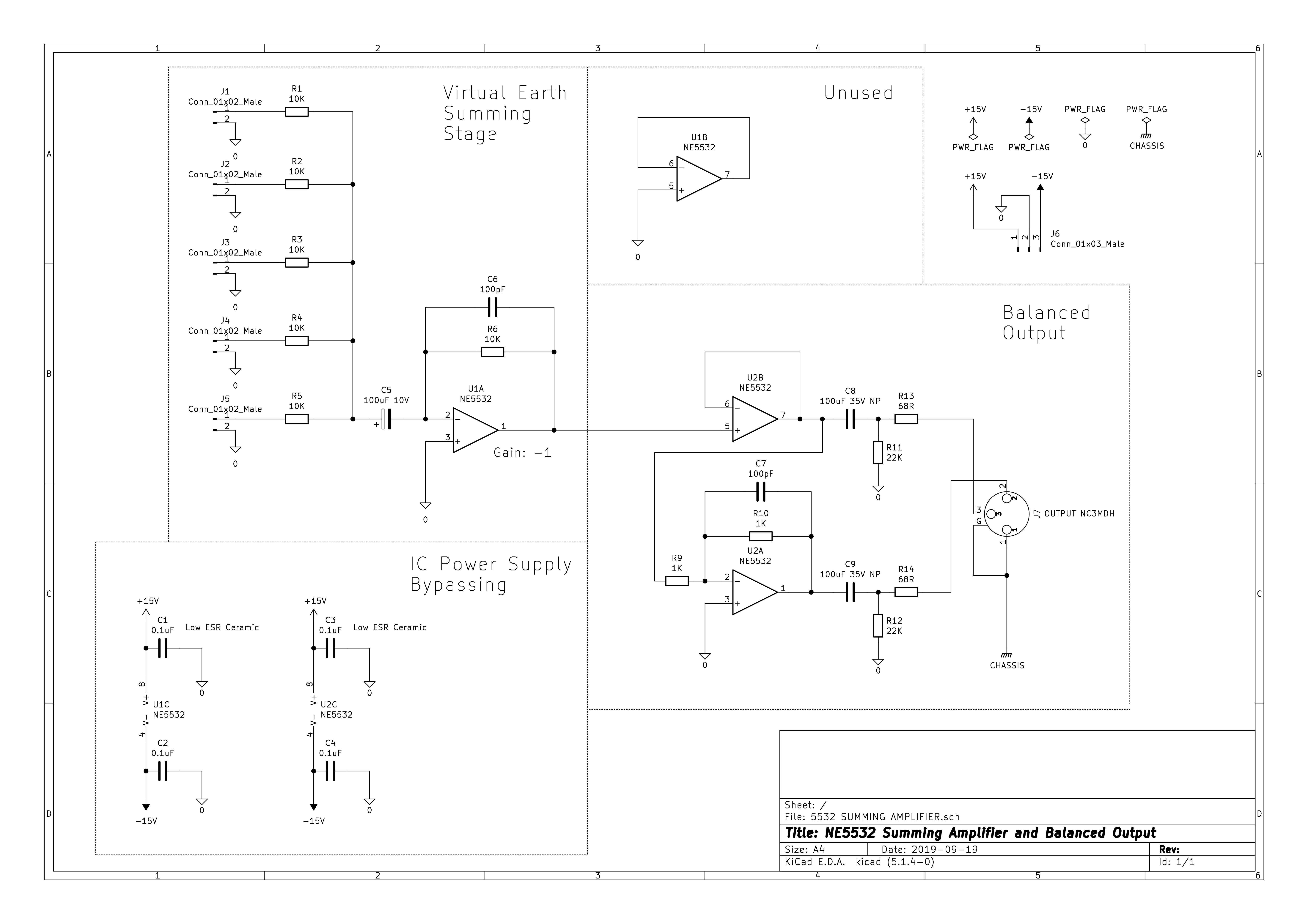
Regarding the mix resistors, the circuit is actually complicated enough that I would model it in LTSpice to see what the currents are, gain structure, noise impact, etc. In particular, unlike the unity signal gain of the circuit, the noise gain is greater and increases with more mix resistors. Note that the load and noise depends on the number of mix resistors. And since 5 is not that many, my guess at this point is that you could probably go down to as low as 6.8K or maybe even 4.7K (five 4.7K in parallel is a load of 940 ohms which a good op amp should be able to handle no problem).

Note that the size of C5 might not matter as much as you think. The resistance seen by that cap is the parallel resistance of all of the mix resistors which is 4.4K. So with a 100uF cap, that's a cutoff of 0.36 Hz. That might seem unnecessarily low but the rationale is that, because it's an electrolytic, it will cause distortion at the corner frequency where it has some AC resistance. However, in this particular virtual earth circuit, the voltage at that point is very low and therefore there will be no significant voltage across the cap and therefore there will be very little distortion. And, if you use a high quality "audio grade" capacitor (which is just a super low ESR cap), distortion will be even lower.

Or, maybe you don't even need the cap at all. The reason it's there is because the offset current of the summing amp may cause popping noises if there are switches directly on the bus. But you don't have switches directly on the bus. Also, you could use a better op amp that has even better performance than the 5532 and lower offset. And, since you got rid of the inverting buffer, you could use a single op amp. There are lots of fancy single op amps that have offsets of 0.1mV or so. I don't keep up on such things but it would not be hard to find an amp that would allow you to remove the cap entirely and still probably do switching directly on the bus.
 
Or just right-size it, without haze, and host on the forum:
 

Attachments

  • 5to1SummingAndBalancedOutput.gif
    5to1SummingAndBalancedOutput.gif
    32.3 KB · Views: 110
Hi to all of you,

trying to finalize this "simple" design: I was wondering about the feed from the summing opamp U1A to the output stage. Is it ok to feed the non inverting input of U2B directly from the output of U1A ?

I will then try to prototype this part of my project and see what new problems arise !

Looking forward to your remarks. Thanks !
 
I keep waiting for Abbey to chime in re. the output circuit design.  So I'm quoting him from another thread here:

https://groupdiy.com/index.php?topic=69902.msg891996#msg891996

"This is one of the worst options for a system output. It's been commonly known as the "Tascam problem". Better use impedance-balanced output (simpler-better-cheaper) or THAT 1646."

I 100% agree.  It wasn't just Tascam.  Avid also used the same bad design.

Bri

 
Better use impedance-balanced output (simpler-better-cheaper) or THAT 1646.
Ah, yes. I forgot about that. I added a switch to my cheap heavily-modded LiveWire DI box to switch to impedance balance. Impedance balanced is definitely the way to go here (unless driving a really long cable). But maybe bump up the 68R to 100R.

But he needs to invert for positive signal to pin 2 hot. So U2A is needed. Meaning drop U2B, feed U2A direct but bump up the 1K to more like 4k7 to reduce load on mix amp. Then just ground inside of C8.
 
Hi !

thanks for your input.

So to put things in perspective, in my project, I'm looking for the output lines to be safe for a 100m cable run.
I do try to understand the basics and choose a suitable output solution.

If I understand you correctly this Douglas Self output stage is not ideal and you point me to  a "well implemented impedance-balanced stage". Could you share example circuits and/or sources of information for me to digest ? What I've read so far is not very clear to me...

Thanks !!!
 
The only way to both drive a long cable fully balanced AND be able to work with an unbalanced load would be to put each output in the feedback of an amp. The "quasi-floating balanced output" in D. Self's book does it. But what does also does it simpler and better is the THAT 1646. I have used THAT 1646 for multiple projects. It's the pro-solution.

Note that AFAIK the only reason to use THAT 1646 vs. the impedance balanced output is that CMRR is better over long runs. But most ground noise is usually just ground loop noise and impedance balanced handles that case quite well. Impedance balanced output is described in D. Self's book in the beginning of the Line Output chapter. Although the figure in my edition does not include the cap and drain resistor. Technically that is slightly better because each line is better matched. But it only marginally improves the circuit so it's usually left out because it's cheaper. But note that without the cap it might matter what "ground" you're connecting to.
 
Thanks Squarewave,

I will read some more Douglas Self then !!! There’s so much to learn !
I’ve had a look at some of the THAT chips which being a little expensive but qualitative, save on space !!!

Thanks again for your input !

 
Ah, yes. I forgot about that. I added a switch to my cheap heavily-modded LiveWire DI box to switch to impedance balance. Impedance balanced is definitely the way to go here (unless driving a really long cable). But maybe bump up the 68R to 100R.

But he needs to invert for positive signal to pin 2 hot. So U2A is needed. Meaning drop U2B, feed U2A direct but bump up the 1K to more like 4k7 to reduce load on mix amp. Then just ground inside of C8.
Hi Bo Deadly, I'm back at this simple project again ! I am designing it with THAT1646 outputs as advised. But just to understand your remark, what did you mean by "ground inside of C8." ?
 
Hi Bo Deadly, I'm back at this simple project again ! I am designing it with THAT1646 outputs as advised. But just to understand your remark, what did you mean by "ground inside of C8." ?

That would only be if you were converting to impedance balanced in which case you could do XLR pin 3 > R13 > C8 > 0V.

But impedance balanced is not going to be good enough for 100m of cable. Not sure if THAT 1646 is good enough for 100m of cable. There's a lot of capacitance in 100m of cable.
 

Latest posts

Back
Top