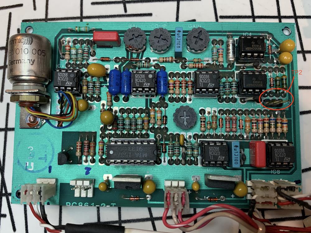
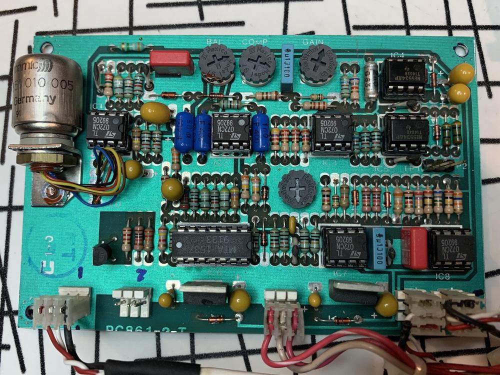
I bought this thing on a fire sale and thought it looked like it could be a fun project. I'm not sure what kind of desk it came out of - the seller didn't have any info - it looks like something from the 80's or 90's. It would certainly by useful to have a schematic, but I think I can make due without.
The questions I wanted to put out there are:
1. Does anyone have any info on this, or know what it is?
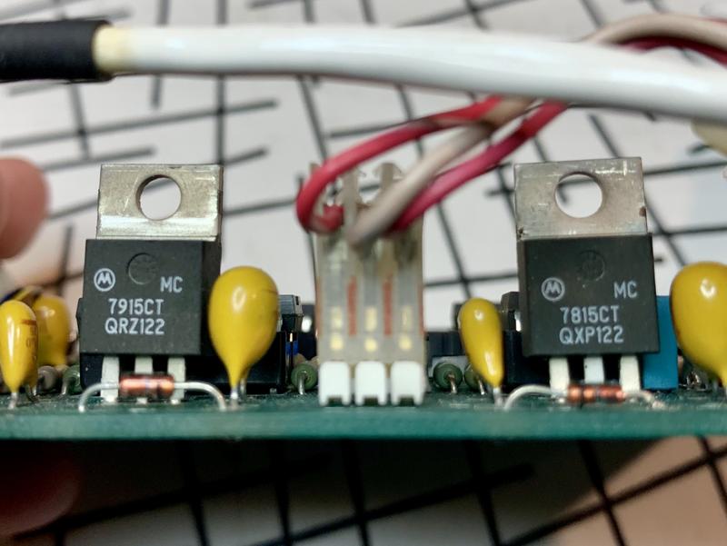
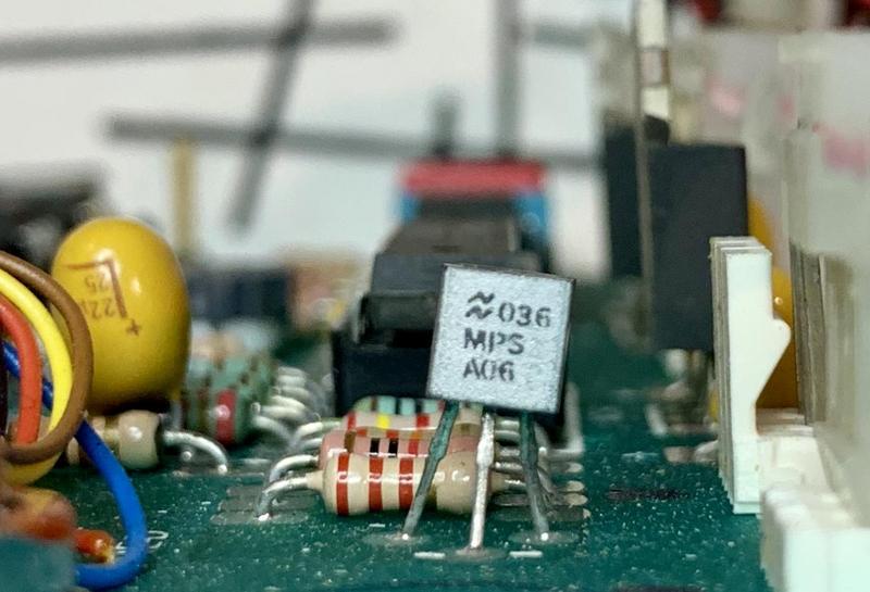
2. How do I figure out what voltage this runs on? I'm assuming I should go through data sheets of the IC's, transistors, and voltage ratings of caps and come up with a number? I believe I've seen most of these chips in consoles that run on +/- 15-18v.
3. Can just I swap the bal/comp/gain variable resistors with panel mount potentiometers?
4. Anyone know what the THLD variable resistor is? You can't see the "THLD" label that well in the photo, but it's the one right in the middle of the board.
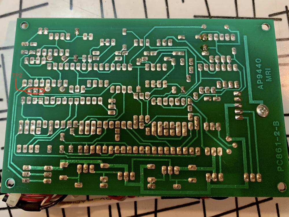
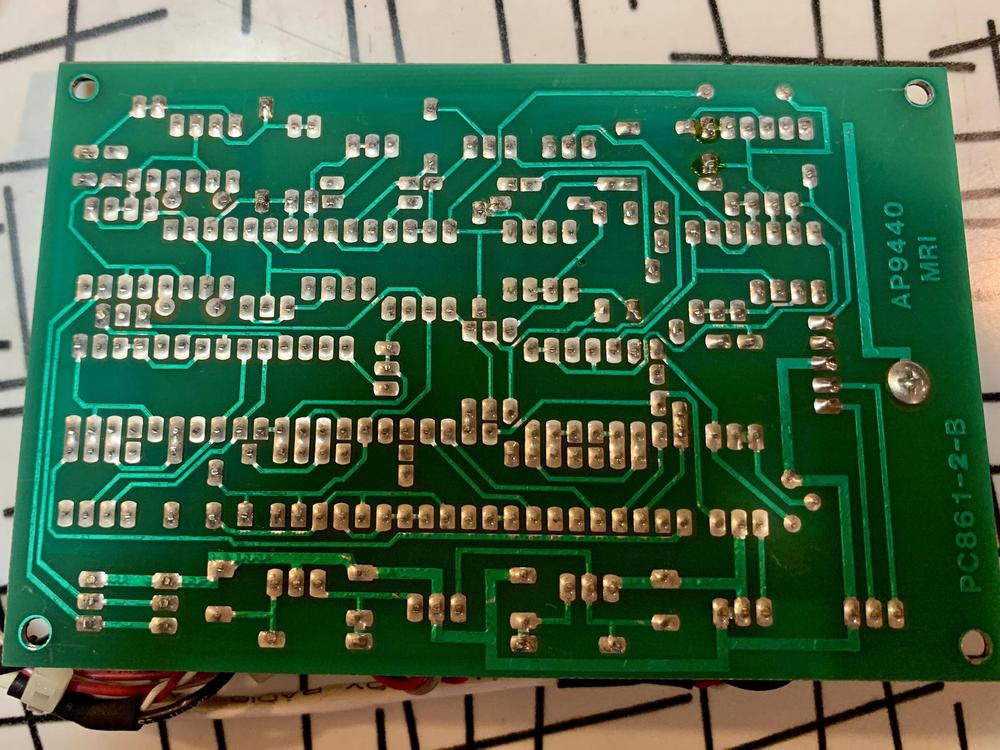
Photos:
Any help would be much appreciated! I'm planning on getting started on this thing next week, but thought I'd put this out here in the event that there are any McCurdy experts out there!
Cheers,
Erik
The questions I wanted to put out there are:
1. Does anyone have any info on this, or know what it is?
2. How do I figure out what voltage this runs on? I'm assuming I should go through data sheets of the IC's, transistors, and voltage ratings of caps and come up with a number? I believe I've seen most of these chips in consoles that run on +/- 15-18v.
3. Can just I swap the bal/comp/gain variable resistors with panel mount potentiometers?
4. Anyone know what the THLD variable resistor is? You can't see the "THLD" label that well in the photo, but it's the one right in the middle of the board.
Photos:
Any help would be much appreciated! I'm planning on getting started on this thing next week, but thought I'd put this out here in the event that there are any McCurdy experts out there!
Cheers,
Erik
")