elskardio
Well-known member
Hi Guys,
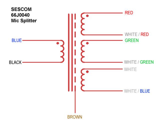
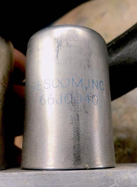
I bought a mic splitter transformer on ebay at a good price. It's from Sescom, model 66J0040. The only info I found is the description from their catalog:
"The models 66J0036A,B (two splits), 66J0040A,B (three splits), and 66J0092A,B (four splits) are specially designed audio transformers used for splitting microphones in remote recording studios, churches and TV production. These transformers have separate isolated electro-static shields to prevent common ground-loop problems. They are enclosed in double shielded nested cans for hum protection. They can also be rotated in their mounting for minimum hum. The Mic-Splitting transformers are designed to be used in a bridging mode to maximize transfer of power without loss of signal or derating performance"
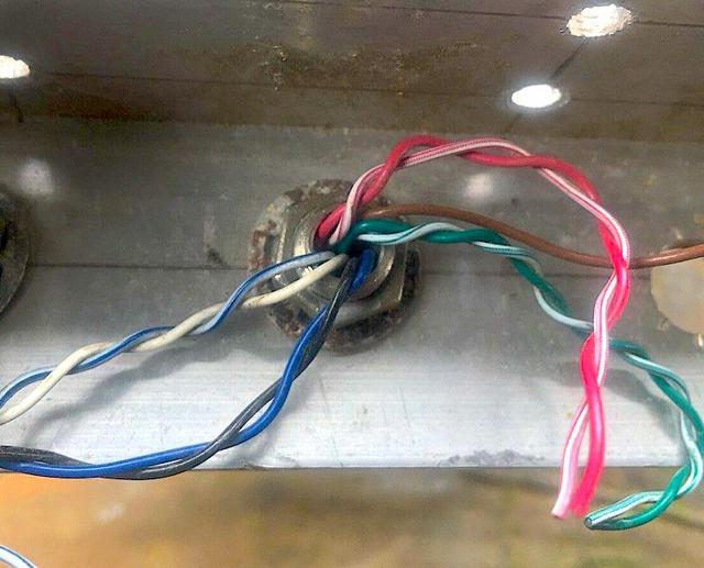
So it should be the three splits. By looking at other sescom transformer on the internet, I tough Black and White were the primary and each color pair a secondary... I ran some test with my generator + scope and I can't seem to find how it's wired.
Anyone has info on this transformer?
Thanks
2 pictures:
I bought a mic splitter transformer on ebay at a good price. It's from Sescom, model 66J0040. The only info I found is the description from their catalog:
"The models 66J0036A,B (two splits), 66J0040A,B (three splits), and 66J0092A,B (four splits) are specially designed audio transformers used for splitting microphones in remote recording studios, churches and TV production. These transformers have separate isolated electro-static shields to prevent common ground-loop problems. They are enclosed in double shielded nested cans for hum protection. They can also be rotated in their mounting for minimum hum. The Mic-Splitting transformers are designed to be used in a bridging mode to maximize transfer of power without loss of signal or derating performance"
So it should be the three splits. By looking at other sescom transformer on the internet, I tough Black and White were the primary and each color pair a secondary... I ran some test with my generator + scope and I can't seem to find how it's wired.
Anyone has info on this transformer?
Thanks
2 pictures: