Add filtering to SMPS power supply

GroupDIY Audio Forum

Help Support GroupDIY Audio Forum:

This site may earn a commission from merchant affiliate links, including eBay, Amazon, and others.

elskardio

Well-known member
Joined
Sep 29, 2010
Messages
575
Location
Montreal - Canada
Hi guys,

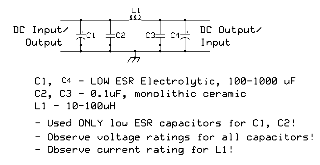
I got 2 smps power supply that I'm planning to use to power 500 racks. I would like to add filtering. Looking at various schematic it seems that a simple one or two stage LC filter could work?

I found a schematic that looks pretty straight forward...

Any suggestion?

Thanks

SMPS-output-filter-1a.gif
 
I was planning to do something similar but haven't tried it yet.  Some things to keep in mind is that SMPS might have a max capacitance load.  They also might have a minimum current requirement, so you want to size them appropriately.
 
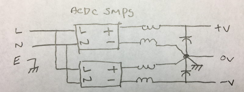
As john12ax7 points out, SMPS actually may not like caps directly on the output. It's not like you're filtering rectified AC. You're trying to get HF hash. And since the inductor will effectively be isolating the SMPS from the cap that follows, I would use a large inductor and small cap instead of the other way around like you're schem shows. I would use the largest inductor you can find with the right current requirements and then just pick a cap that gets down below 20Khz. For example, you should be able to get at least 1mH which with a 10uF cap gets you down to 1.5kHz. You might also use a common mode choke but I have heard people say it doesn't matter. Personally I always liked the idea of using a common mode choke to completely isolate both outputs of the SMPS and then use the point right after the choke as 0V and star ground point. Same applies if you're stacking two to make bipolar. You'll just need two chokes. Of course SMPS must be isolated type.
 
john12ax7 said:
Some useful info here
https://www.proaudiodesignforum.com/forum/php/viewtopic.php?f=7&t=943&hilit=meanwell

Good info! Thanks

squarewave said:
Same applies if you're stacking two to make bipolar. You'll just need two chokes.

Thanks for the detailed explanation.

How do you implement the common mode choke with a dual rail power supply? I can't find any schematic in a bipolar configuration.
 
Ive tried a common mode choke followed by two caps back to back  then two differencial mode chokes one in series with each leg  finally a cap across the output ,got me about 30db reduction according to  the multimeter , I used larger caps as I was feeding it off a conventional linear psu (transformer/bridge/reg) and I wanted  the filter to be effective down at 50 and 100hz . 
Maybe a modified mains RFI filter with cap voltages and values in a more appropriate range for what your doing might be interesting to try , making everything sheilded and symetrical could help gobble up even more RF hash .
I typically reuse mains common mode inductors from old Smpu's for these type of low voltage filter ,larger toroid type coils are good if you can get them , but smaller ferrite bobbin core types work just as effectively with smaller currents .
 
elskardio, what output voltage and current ratings do the smps have? 

Are you using smps that come with a reasonable specification/data sheet, or just something without compliance or anything but basic ratings?

What aspect of the smps spec data indicates you will need to add additional filtering - the mains frequency related ripple voltage spec or some aspect of their EMC performance, or is it smps switching ripple related, or is it just a feeling you have in your bones?

What equipment is in your '500 racks', and is that prone to ground loops, or is the power supply the only connection to ground, or will you float this common dc supply?
 
I have also been considering doing something similar with the RID-125-1248 smps. After reading the proaudiodesign forum thread (Thanks John), and comparing the RS-25-48 datasheet (mentioned in that thread) with the RID-125-1248 datasheet, I was thinking of trying a 3 - 4 mH common mode choke together with a 1000uF/50V cap (on each output). I was going to try using the 12V output for meters.
 
When using a floating output smps, like the meanwells and those tested in the proaudiodesign forum, the appearance of mains frequency related hum in the spectrum down near the noise floor can be influenced by the grounding scheme of the smps, and the measurement system.

One of the thread posts also identifies some smps switching frequency artefacts near 50kHz.  Similar to mains hum levels, some care is needed to correctly measure that, and even not to miss seeing something if it is above 48kHz (if your spectrum analyser only goes up that far).  Whether some artefact well above the audio range, and nigh on in to the noise floor is a 'problem' for you is a separate matter I guess.
 
Squeaky said:
I have also been considering doing something similar with the RID-125-1248 smps.
That's a pretty big supply. Do you really need 2A of 48V? That's enough for ~140 phantom power loads. Note that you have to load with at least 10% or so or you might get LF modulation noise so the bigger the SMPS the high wattage load you need. Depending on how many meters you have even a small 48V SMPS with a zener to make 12V would probably be enough. APC-16-350 is 350 mA which is enough for 20+ phantom power loads. If you have fewer loads than that, you could make 50mA of 12V with 5W zener and still have enough juice for 15+ phantom power loads. Or use separate SMPS. The supply you're looking at is 140 watts!
 
Thanks for the comments Squarewave, appreciated. I don't want to open a can of worms about well designed power supplies, &c (I am sure what I am trying to do could be done enormously better in a plethora of ways) but I thought I might try and explain myself. I want to use the 48V supply to generate other voltages. I already have at hand a number of power supply kits (JLM TREX2) that generate two voltage rails from a 48V supply. Budget is tight, I already have a few of these supplies built, so I want to try and use them. For my project (a small mixer) I need 48V, 36V and 24V (as well as the 12V for meter buffers and lamps). There will be something like 20 meters altogether? I was going to have the switch mode supply (and the common mode chokes (and capacitors, if required)) in a box external to the mixer, run in the 48V and 12V to a power distribution center inside the mixer where some of the power supplies are located and then run out voltages (4-core cable: 0V, 48V, 36V, 24V) to modules from there.  There will also be a 10r, 470uF RC filter onboard each mic pre module (as required) for the phantom supply. The master section will have its own dedicated TREX2 on board as will the aux returns module (these are being built in rack mountable cases). Some modules do not require 48V (e.g. the master, return and send modules as well as some other line level modules I'm building). Probably would be more elegant just to use a zener drop the 36V to 24V onboard modules as required? At least the trim pots on the TREX2 supplies allow for a reasonable degree of accuracy, and anyway, the die is cast. A 24V line will also be run out of the mic/line module up to a separate router module. It is all pretty low tech with cables and connectors. Everything is being built very modular so I can keep pulling it apart and putting it back together.

I have often read that switch mode supplies prefer to run somewhere around their designated current rating and I am trying to keep this in mind. I have estimated the system current requirements (quiescent current draw for the amplifiers and 10mA for phantom) at maybe just under an amp for the console and slightly more for the meters and buffers? The SMPS will be running at about 40 - 50% of rating? The RID-125-1248 looked like it might work and is cheap enough to give a go.

I have read that phantom supply should be kept separate from other supplies and I am wondering about this. I have a suite of other questions that I still need to answer.

I used something like the RS-25-48 (380mA version) onboard with a TREX2 in a single mic pre eq test module for 48V, 32V and 24V and it worked really well and was very quiet. I guess my thinking was to take the SMPS external to the module, make it bigger, create a distribution network, run cables to multiple modules, and hope a bit. Its all about the journey right?

Apologies for the long-winded post.
 
I have done what you're describing but only for a tiny little dual mic pre. I'm not sure it would work well for a whole mixer. The reasons are:

1) If you split the 48V then you can't make 48V relative to the virtual ground. The phantom power return must be to the negative rail which is to say the chassis must be connected to the negative rail which is to say you cannot connect the virtual ground to the chassis (because you would short out the lower rail). It's not clear that you can do that with the TREX2 since the virtual ground and chassis ground cannot be connected together.

2) If you use a resistor to "drop" 48V to 12V for example, the voltage will depend on how much current is being drawn through the resistor (ohms law). That's not good. You can use a zener but even then you'll need to probably regulate it with at least a capacitance multiplier. Also, you should realize that if you draw 100mA from the 12V, the power dissipated will be like 100mA at 48V and not 12V. Meaning you're dropping 48 - 12 = 36 * 100mA = 3.6W. So you're going to burn 3.6 watts just dropping the voltage. That zener is going to get HOT.

For something complex like a mixer, this sort of thing is not recommended. It would be greatly superior to stack SMPS. For example you could use 2 x 24V, make a proper virtual ground just like in the graphic like I posted and then regulate down to +-15 or whatever the circuits call for. Then add a v. small 48V SMPS for phantom. But you should really consider what uses the most current and try to get as close to that voltage as possible (again because dropping too much will dissipate a lot of power). So if you have lot's of high current 12V stuff, you should probably also have a 12V supply.

In other words, you should use multiple small SMPS and not one big one. Fortunately even the really good ones are pretty cheap so they're great for DIY.
 
trobbins said:
Are you using smps that come with a reasonable specification/data sheet, or just something without compliance or anything but basic ratings?

What aspect of the smps spec data indicates you will need to add additional filtering - the mains frequency related ripple voltage spec or some aspect of their EMC performance, or is it smps switching ripple related, or is it just a feeling you have in your bones?
Unfortunately, most of the commonly available smps specifications are too vague to provide useful understanding. One particular issue is radiated emissions, which is not an issue when using a single smps, but becomes one when you start combining 4 or 5 of them. I wouldn't rely on published specs to make an opinion on the suitability of an smps. Experimentation is the only way to guarantee results. Even relying on other people's expertise is not always safe, because changes in implementation and application can make a big difference.
And of course, since it relies on mostly unspecified parameters, you're at the mercy of any ECO at the mfgr's site.
 
How is anyone going to experiment in a way that confirms compliance with radiated EMI standards?  Perhaps cheapest path is to pay for a pre-compliance check from an approved test-house.    Very few, if any, would have an open-air or shielded room setup for radiated testing to standards.
 
trobbins said:
How is anyone going to experiment in a way that confirms compliance with radiated EMI standards?  Perhaps cheapest path is to pay for a pre-compliance check from an approved test-house.    Very few, if any, would have an open-air or shielded room setup for radiated testing to standards.
The issue there is that compliance to radiated emissions is not a guarantee of quiet operation of the complete system. I would think one can generally trust the manufacturer's certificate for separate components, but for the whole build, nothing replaces an actual test, and our test would be quite different than a UL/CSA or CE test. Us audio guys actually don't care if our emissions down planes or start a nuclear attack, as long as our signal is clean.  ;D
 
Hi guys,

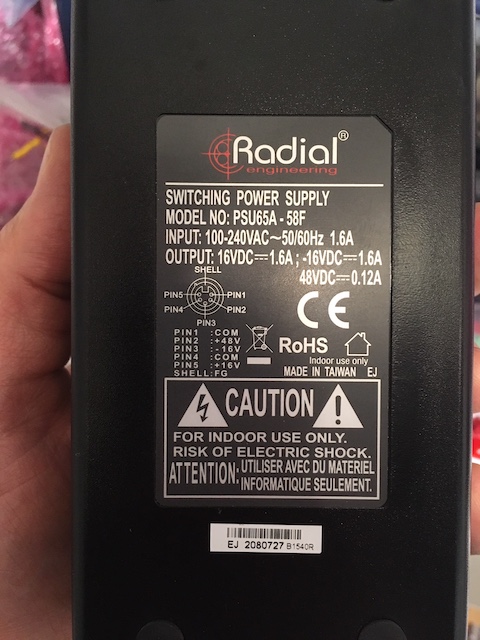
I got a good deal on a Radial power supply. It's the one they use with the Cube and SixPack.

radial-smps.jpg


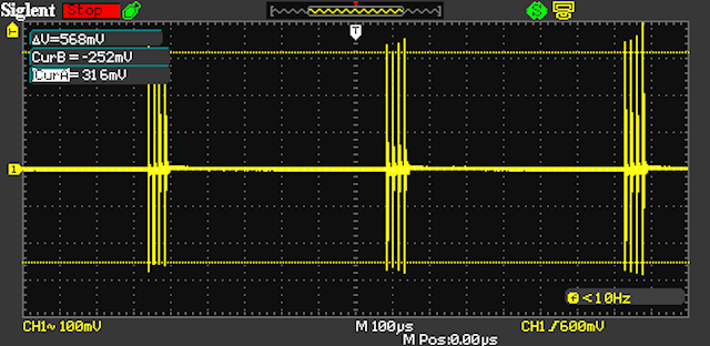
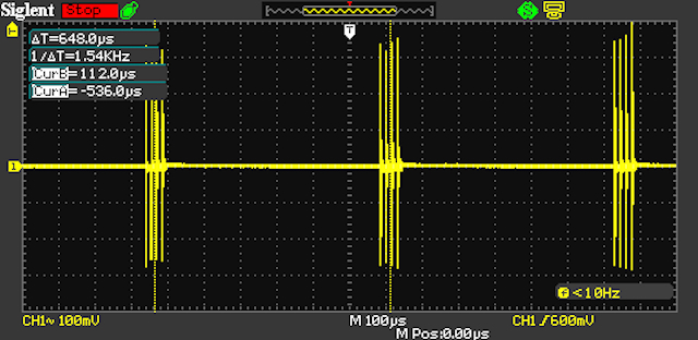
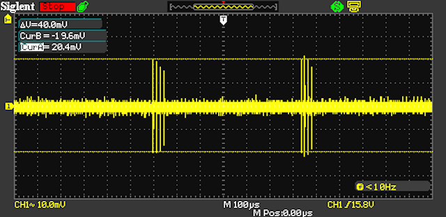
Before using it I decided to connect it to my scope to see if there were any noise... To my surprise there's major ripple at 1.5kHz. Close to 600mV. The scope was is Peak mode when I took the following snapshot:

SDS00004.jpg

SDS00005.jpg


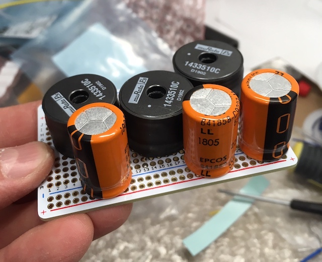
I built 3 simple LC filter (one for each rail) using 3.3MH inductors and 220uF capacitors. Here's the result after the filter:

filter-pcb.jpg

SDS00007.jpg


Down to 40mV. close to 23dB of attenuation

My friend has a Radial SixPack and he said there's nothing inside the rack between the power connector and the 500 slots...

Next, I have to run some test with 500 modules and audio to see if it makes any difference. Filtered or not.

Cheers
 
Thanks for sharing the results.  You might also try loading the supply to see if it improves things.

There was a threat on here somewhere describing the radial racks, think some had common mode chokes for filtering.
 
Back
Top