You are using an out of date browser. It may not display this or other websites correctly.
You should upgrade or use an alternative browser.
You should upgrade or use an alternative browser.
EAB MV63 Inductor Value
- Thread starter Murdock
- Start date


Help Support GroupDIY Audio Forum:
This site may earn a commission from merchant affiliate
links, including eBay, Amazon, and others.
> What is the input and output impedance of the filter?
What is rp is EF806s? The inductance of DV41 may matter. Parts 30 and 31 are in there also. Tube 42 is worked with NFB so approaches 200k input.
I basically just figured 120Hz with 5,000pFd to get an L. This may be 2:1 off, or more, either way. But it does mean a chunky part, not a tiny doughnut.
What is rp is EF806s? The inductance of DV41 may matter. Parts 30 and 31 are in there also. Tube 42 is worked with NFB so approaches 200k input.
I basically just figured 120Hz with 5,000pFd to get an L. This may be 2:1 off, or more, either way. But it does mean a chunky part, not a tiny doughnut.
Ive got about 20 hy off a small rewound mains tx , typically a modern transformer has a split bobbin to keep pri and sec well apart .
If you dont have access to a winder of some sort , you could dismantle two identical transformers , take the primary winding from each , and mount both on one of the cores ,then wire them up in series . Doing that gave me around 5hy with butt stacked lams , with the lams interlaced got around 20hy ,with a total of about 6kohms dc resistance in the two coils. Im unsure if you need it gapped or not , if you do your going to need a larger or more exotic core material to get the same HY.
If you dont have access to a winder of some sort , you could dismantle two identical transformers , take the primary winding from each , and mount both on one of the cores ,then wire them up in series . Doing that gave me around 5hy with butt stacked lams , with the lams interlaced got around 20hy ,with a total of about 6kohms dc resistance in the two coils. Im unsure if you need it gapped or not , if you do your going to need a larger or more exotic core material to get the same HY.
PRR said:> What is the input and output impedance of the filter?
What is rp is EF806s? The inductance of DV41 may matter. Parts 30 and 31 are in there also. Tube 42 is worked with NFB so approaches 200k input.
I basically just figured 120Hz with 5,000pFd to get an L. This may be 2:1 off, or more, either way. But it does mean a chunky part, not a tiny doughnut.
Thanks! But which formular did you use? If I use a second order cl high pass filter calculator with 5000pF and 120Hz I get about 350H...
What kind of filter is this?
It's a 3rd order filter with different input and output impedances. The inductor should be about 150-200H.Murdock said:Thanks! But which formular did you use? If I use a second order cl high pass filter calculator with 5000pF and 120Hz I get about 350H...
What kind of filter is this?
abbey road d enfer said:It's a 3rd order filter with different input and output impedances. The inductor should be about 150-200H.
Thanks for the answer!
Can you please elaborate on how you calculate that? How do you know the in and output impedance? I would like to simulate it in spice for different frequencies.
150-200H seems rather high for just a lowcut filter. Could i increase the two capacitors and decrease the inductor value for the same frequency?
I cheated! I used a calc.Murdock said:Thanks for the answer!
Can you please elaborate on how you calculate that?
http://www.carstereo.com/help/Articles.cfm?id=10
I had to scale the values because with 200kohms the capacitor values were smaller than the calc's resolution; the result was zero, so I entered 200 ohms and the results were in nF instead of uF.
There are math formulae, but they are rather obscure when the input and output Z's are different; the two readable cases are for equal Z's or zero source Z.
The output of the filter sees a Virual Earth stage with an input resistor of 200k. The input impedance of a VE-based stage is more or less that of the resistor that feeds it.How do you know the in and output impedance?
The preceding stage is under NFB so its output impedance is much smaller than the load impedance of 200kohms, I would think less than 10k.
Thus I ASSumed the x-over calc would give realistic results, because it presupposes the source impedance (an amp output) is much lower than the speaker load.
Actually, that's what I did in order to ensure I had not make a stupid power of 10 mistake, which is what happens frequently when scaling.I would like to simulate it in spice for different frequencies.
Indeed.150-200H seems rather high for just a lowcut filter.
That would increase the load presented to the preceding stage (increase load=decreasing the impedance); you would then run into headroom problems. You would also need to increase the output load of the filter, because with smaller L and larger C's, the damping factor would decrease seriously, resulting in a sharp hump at the turnover frequency. that would be easy but it would result in significant attenuation.Could i increase the two capacitors and decrease the inductor value for the same frequency?

There's a significant difference, the input and output Z's are identical; there are two 40k resistors feeding the filter, so they don't worry about loading the preceding stage, whatever the loss is, they compensate it in the subsequent stage.CJ said:here is a similar situation with the 76>
As a result they can get away with a 50H coil.
> ensure I had not make a stupid power of 10 mistake, which is what happens frequently when scaling.
Indeed. I seem to have screwed a decimal when I offered "10H". However if Murdock had just dropped *any* roughly 10H coil in the breadboard the error and fix would already be known.
One way to avoid decimal point confusion is a REACTANCE CHART. Print a few and keep them on the desk. We suspect the load is near 200k (200k into an imperfect virtual earth, plus 1Meg in ||). Draw the 200k line. The source appears to be largely a triode plate resistance, goosed-up by unbypassed cathode resistor, with also 47k and a cap. I drew a line at 40k. There are two 5000p caps and as far as the coil knows, they are in parallel (though with different series resistances). So pencil 10,000p(0.01uFd). And the claimed frequency is 120Hz, pencil that line.
With that construction we see that a likely value of L is 200H (and I did drop a decimal). The Qs are around unity which seems likely. The several undetermined resistances mean this is not a final value, but you need to be in that "150-200H" zone proposed by Abbey.
This is all rough-guess analysis. There IS a better way: breadboard it!! It's not that many parts. The problem is moot unless you are going to BUILD (or repair) it. So why talk about it when you can TRY it?
Attachments

This is all rough-guess analysis. There IS a better way: breadboard it!! It's not that many parts. The problem is moot unless you are going to BUILD (or repair) it. So why talk about it when you can TRY it?
A distant 2nd-best is the Idiot Assistant. SPICE won't know about the real circuit's values or parasitics, and it is about as tedious to set-up this filter as to solder some resistors. However SPICE will give an 8-digit correct answer to the problem you put to it. Some fooling with SPICE gives 150H for -3dB @ 118Hz. Ooops, that big an L will have large R. Adding 10K to the choke shifts F to 123Hz, no big change.
Obviously some factory had a fine-winding operator who was not busy. Not only Bv506 but also DV41 are real special-parts.
Attachments

Except there's global NFB around; if there wasn't, what would be the use of the 2uF cap (marked 22)? That's why I penciled "less than 10k". Actually, it isn't significant; who said 120Hz is a magic number?PRR said:The source appears to be largely a triode plate resistance, goosed-up by unbypassed cathode resistor, with also 47k and a cap. I drew a line at 40k.
> there's global NFB around
Oh, so you think if I give SPICE the wrong problem it will give a right answer to that wrong problem?
This is easier. Scrap tube and battery, throw in a non-zero source impedance. Result is not very different. (This run includes some DCR in the coil so 123Hz is same-as the unposted sim with DCR.)
Slope is 20dB/octave as far as I see. We know it will be 18dB/oct in the long run but the bump skews the part that matters. Seems a very elegant design. Still expensive (unless Ernest is sitting there at the winder with nothing to do...).
Attachments

Correct; I didn't notice the 47k resistor. Duh!PRR said:> there's global NFB around
Oh, so you think if I give SPICE the wrong problem it will give a right answer to that wrong problem?
Wow, thanks alot for the informative answers!
I would like to simulate most of the circuit before I buy the parts.
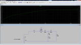
Strangely I get very different results when I simulate in spice.
This is 24dB down at 100Hz...
Can you see what I missed in my circuit?
I would like to simulate most of the circuit before I buy the parts.
Strangely I get very different results when I simulate in spice.
This is 24dB down at 100Hz...
Can you see what I missed in my circuit?
your sim directive should be in octaves not linear; type .ac oct 50 20 1kMurdock said:Wow, thanks alot for the informative answers!
I would like to simulate most of the circuit before I buy the parts.
Strangely I get very different results when I simulate in spice.
This is 24dB down at 100Hz...
Can you see what I missed in my circuit?
abbey road d enfer said:your sim directive should be in octaves not linear; type .ac oct 50 20 1k
Yep, that was it. Thanks alot!
moamps
Well-known member
Could you please post the whole schematic of the preamp?Murdock said:looking at the EAB MV63 schematic.
Similar threads
- Replies
- 2
- Views
- 864
- Replies
- 16
- Views
- 1K