


Trying to wrap my head around the math here, and making sure I'm not missing something. In a 'swinging input' EQ like the API 553:
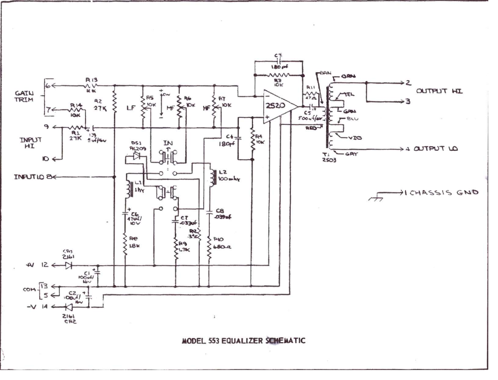
The low band is a 1H inductor, 47uF capacitor, and 1.8K resistor in series. By my calculations, the resonant frequency would be 23Hz, with a bandwidth of ~290Hz. I'm guessing this was done to make a pseudo-shelf control - the dip starts at around 165Hz and acts like a shelf in the audible band.
It seems like it would be a lot easier to use something like a 100mH inductor, a 100uF cap, and a 120R resistor. That would yield a center frequency of 50Hz, and with bandwidth of ~190Hz, which would have the dip start at around 145Hz, and look fairly similar below that. It would cut slightly less between 20Hz and 50Hz than the original, but only marginally so, and would use a much easier to find 100mH inductor.
Am I missing some important point here?
The mid band make sense to me. A 100mH inductor, 39nF cap, and 680R resistor yield a center frequency of around 2.5KHz, with a bandwidth of about 1080Hz - pretty sensible.
The top band has me confused too though. Because this is a simple RC band, rather than an RLC band, I figured I should use the standard RC equation, f = 1/(2π * R * C) - but with C = 33nF and R = 1300, that gives me a frequency of 3710Hz, which can't be right. This is clearly not a standard RC low pas circuit anyway. How do I calculate the frequency and bandwidth of the RC high band?
")

