Mysterious random noise in custom summing mixer

GroupDIY Audio Forum

Help Support GroupDIY Audio Forum:

This site may earn a commission from merchant affiliate links, including eBay, Amazon, and others.

Aleguitarpro

Well-known member
Joined
Dec 28, 2011
Messages
179
Location
ITALY
Hi
Just finished a 16 channel summing mixer made with NE5532/5534 input stage, an additional active "gain" stage for saturation, very easy summing section etc etc.

The summing mixer works perfectly.
Global power consumption is about 800 mA per rail (+16/-16).

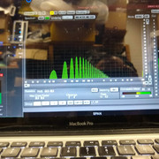
I have this problem: when I engage all the 16 additional gain stages on each channel this noise (ripple?)  passed trough audio line.


At the beginning of the building I used 317/337 for PSU with big filtering caps (10.000uF on each rail).

Now I tried to use this power supply (it's super oversized for this project):


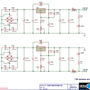
and the problem starts random after 14 of 16 additional gain stage on.
But this additional gain stage is always powered, it's only "audio" bypassed.

Any idea?
I never had this kind of noise before but it's for sure related to power supply.
The mysterious part of the problem is that sometimes disappear with all the additional gain on.
Sometimes appear with 12 of 16 channels gain "on".
I think is related to ripple but I tried to work on filtering and at the beginning it helps.
Now I'm at 4700uF+4700uF+3300uF on each rail after diode bridge and 1000uF in parallel with 100nF after regulators.

The only thing that change the power consumption are the leds that are on with the additional gain stages on.
So in total a change of 16x10mA on the +16VDC rail only.

Power transformer is rated for 1.6A per secondary and only with this absorption of 800mA start to gets warm a little.

Thanks for  help!
 
Looks like all harmonics of 50Hz which certainly suggests mains.

My wild guess: Because the LEDs are only drawing from the +16V rail but the 1.6A rating is for the entire secondary, your power supply is out of balance more than you think. Try disconnecting the LEDs entirely. Does the problem persist? If you re-add a resistive load to only the +16V rail of 100 ohms 5W (or maybe lower like three 1/2W 220 ohm in parallel briefly) does the problem re-appear?

Unfortunately there's no really great solution for this. You could make a virtual ground with a PNP power transistor and 10K resistor to dump the current into the negative rail. But that's a little crude (at the very least a waste of power).

Ideally you should have a separate supply for LEDs and relays and such things. I use 5V because it's also good for micros and logic and such. Is your PS external or internal? MeanWell make lots of little PCB mount 5V SMPS supplies that could easily power those LEDs and on an isolated ground. The only problem is that it might radiate noise into nearby circuits if it's physically too close. But if you can put about 200mm or so between it and anything sensitive, I think it would work great.

But again, this is largely a wild guess at this point. It could be just bad grounding. I just wrote a longish general post about that here two days ago.
 
Did you follow the regulator manufacturer's recommendations exactly? It may be relevant what type of cap (normal or low-ESR electrolytic, tantalum, ceramit, poly) is used there.

What's the decoupling scheme on the channels? Do the individual channels have dampling resistors in series for their power lines? Unless the op amps are decoupled from each other this way they may oscillate together.

What types of caps did you use for decoupling and how? What's the grounding scheme? I found that separate decoupling (dirty) grounds that go separate all the way to a star point on the console frame can lead to instability in my console. I would recommend to decouple each 5532/5534 with 10uf (standard, not low-ESR) electrolytic caps and parallel 100nf X7R caps, 3 each going from + to ground, - to ground and between + and -. Rail-to-rail (+ and -) decoupling in my experience makes the 5532/5534 run smoothly but may lead to instability in other caps (OPA2134 comes to mind). If the op amps on a channel are not far apart it might be enough to use just one cap for each function, except for the rail to rail decoupling ceramic, which should be applied to every 5532/5534.

Use a ground separate from audio ground that joins at the channel ground connection. Use a star grounding scheme (not daisy chain) for the channel grounds.

 
Thanks, good to know how to decouple better ne5534/5532.
I used on every opamp 0.1uF C0G capacitor and on every board a local 10uF low esr cap.

I have schematics hand written but I'll try to scan something.

I thought to put LEDs on a different power supply rail but their power consumption is only 160mA when they are all powered.

Now everything works flawlessly. I tried to reduce power supply per rail at about 15.5vdc
A small change but the problem disappeared.

I have 15vac toroid and specs are 1.6A per secondary (3.2A total).
When the LEDs powered I have a total power consumption of 800mA but the 2 rail are unbalanced (about 320mA for -15.5vdc and 480mA at +15.5vdc).

This unbalancing at VAC could cause this ripple?

Thanks for help
 
After diode bridge I measure 21.2vdc.
LM350 dropout voltage to be safe is about 3v isn't it?

So I could regulate at 16vdc without problems, no?
But reducing at +/-15.5vdc solve the noise problem but I want to understand why
 
Aleguitarpro said:
After diode bridge I measure 21.2vdc.
LM350 dropout voltage to be safe is about 3v isn't it?

So I could regulate at 16vdc without problems, no?
But reducing at +/-15.5vdc solve the noise problem but I want to understand why
That symptom supports my earlier suggestion of regulation dropping out from inadequate unregulated voltage.

If the regulator dropout voltage is 3V that means the unregulated needs to be "clean" 3V above the output voltage. This means that the bottom of the ripple dips on the reservoir caps need to remain above that minimum dropout voltage. 

If you do not have a scope, perhaps measure the AC voltage riding on the unregulated (some cheap VOM have difficulty with such measurements). You could trick a cheap VOM by using a capacitor in series with the VOM in AC mode to make a measurement of AC riding on DC.

JR 
 
Aleguitarpro said:
After diode bridge I measure 21.2vdc.
LM350 dropout voltage to be safe is about 3v isn't it?

So I could regulate at 16vdc without problems, no?
But reducing at +/-15.5vdc solve the noise problem but I want to understand why
That is kinda strange. Is the 21.2V with load? I would think you should be able to get to 16V or maybe even 17V. Not familiar with LM350 though. Note that you'll need a heat sink (or, if it's surface mount, a lot of space with copper planes on top / bottom filled with vias).

An imbalance of 480mA / 320mA should not be a problem for a 1.6A supply.

Make sure your ground wires are hefty (like 20 AWG or maybe even 18 AWG).
 

Latest posts

Back
Top