bluebird
Well-known member
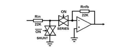
Can anyone recommend a good bilateral (analog) switch? Preferably +/- 18V, low distortion, quad or more...
Something like the old CD4066 that I can use for full voltage audio.
Thanks!
Something like the old CD4066 that I can use for full voltage audio.
Thanks!