


Hey guys,
I've had an idea I'd like your input on.
A while back there was a thread where someone was asking about passive compressor designs and more specifically possible compression using capacitors. In this thread Jakob hinted that there was no passive way of doing this, but that compression should be possible using varactors in an RF-circuit. Now that idea kind of stuck with me and I started looking into RF-modulation/demodulation and how varactors are integrated into oscillators tank circuits, but I couldn’t really find a way to make a compressor work in this domain, at least nothing, that was actually making use of these techniques.
Nevertheless when browsing through mic schematics and specifically pads in mic designs it hit me: shouldn’t it be possible to use a varactor in conjunction with another capacitor to form a capacitive voltage divider and achieve compression this way?
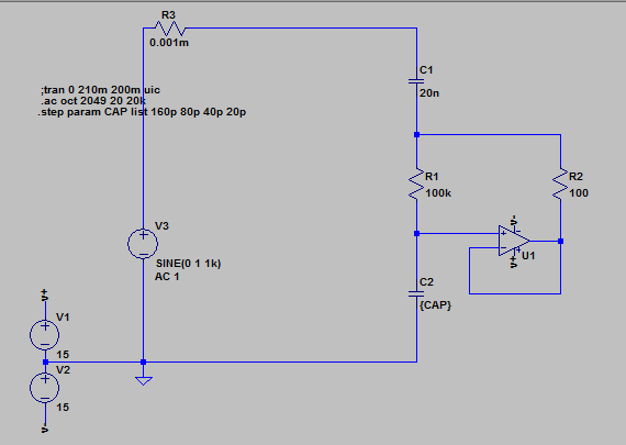
So I thought maybe something like this would get me started: a simple sidechain like Fred Forssell’s opto-sidechain with an added DC-offset in the end to lower the varactor’s capacitance. Then the control voltage has to be negative so that it subtracts from the positive DC-offset, decreasing the width of the depletion region and upping the capacitance. Since afaik the capacitive voltage divider is calculated as C1/(C1+C2), the AC input signal should be lowered when C2’s capacitance rises, which in this case would be formed by varactor and a bypass cap in series.
I attached a mockup of the basic idea in Eagle and just wanted to know if this would work in principle or if I'm just missing something. Is there a reason I've never seen this before?
Best
Jannis
I've had an idea I'd like your input on.
A while back there was a thread where someone was asking about passive compressor designs and more specifically possible compression using capacitors. In this thread Jakob hinted that there was no passive way of doing this, but that compression should be possible using varactors in an RF-circuit. Now that idea kind of stuck with me and I started looking into RF-modulation/demodulation and how varactors are integrated into oscillators tank circuits, but I couldn’t really find a way to make a compressor work in this domain, at least nothing, that was actually making use of these techniques.
Nevertheless when browsing through mic schematics and specifically pads in mic designs it hit me: shouldn’t it be possible to use a varactor in conjunction with another capacitor to form a capacitive voltage divider and achieve compression this way?
So I thought maybe something like this would get me started: a simple sidechain like Fred Forssell’s opto-sidechain with an added DC-offset in the end to lower the varactor’s capacitance. Then the control voltage has to be negative so that it subtracts from the positive DC-offset, decreasing the width of the depletion region and upping the capacitance. Since afaik the capacitive voltage divider is calculated as C1/(C1+C2), the AC input signal should be lowered when C2’s capacitance rises, which in this case would be formed by varactor and a bypass cap in series.
I attached a mockup of the basic idea in Eagle and just wanted to know if this would work in principle or if I'm just missing something. Is there a reason I've never seen this before?
Best
Jannis

")