525C

GroupDIY Audio Forum

Help Support GroupDIY Audio Forum:

This site may earn a commission from merchant affiliate links, including eBay, Amazon, and others.

dogears

Well-known member
Joined
Nov 15, 2017
Messages
548
Location
Texas
So I've been staring at the 525C for a while today and I have a couple of questions.

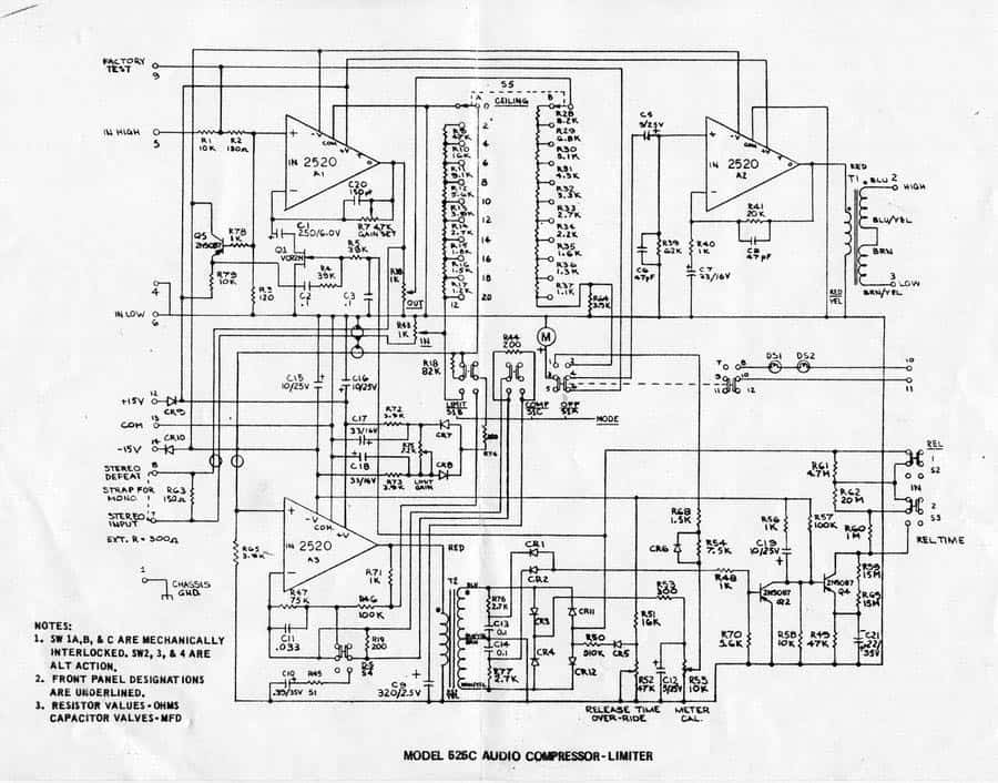
I'm trying to figure out how the ratio works out - why limit is 20:1 and compress is 2:1.

If you consider the "ceiling" to be set to max, the sidechain input shorts past R18 on the original schematic, and then the only change to the sidechain between the two modes is the gain around the op amp. It changes from roughly 48 dB in compress to 54 dB in limit.

If you wanted to get ratios between 2 and 20... would you just change the gain on the driving amp accordingly?
 

Attachments

  • both.png
    both.png
    17.2 KB · Views: 37
Here's a simplified re-draw of the schematic. Some values may be wrong, I've been poking around in the sim.

And the original hosted by Dan Alexander
525Cschem.jpg
 

Attachments

  • 525 simplified.pdf
    128.9 KB · Views: 16
Pretty conventional JFET shunt gain element. In this case the variable R from the JFET increases gain with lower resistance.

A few observations

#1 the audio seen by the JFET is padded down by a resistor divider for lower distortion (tradeoff is higher noise from the make up gain).

#2 negative feedback causes the op amp - input to precisely follow the + input. Q5 forms a simple emitter follower to cap couple 1/2 the AC voltage present on the drain to the gate. So the attenuated AC signal from the drain rides on top of the DC control voltage to linearize the JFET (old trick).

#3 the side chain looks conventional but not simple... You will notice a trims for meter cal because JFET R vs Vgs is not standardized, but varies between parts.

====

People more familiar with this approach may explain details better, I have mainly used JFET for simple lower performance applications.

JR   
 
dogears said:
Thanks John. What sets the ratio here? Is it just the sidechain op amp gain?

My understanding is that ratio is varied by altering the side chain gain after the thresholding device (diodes usually).

Cheers

Ian
 
dogears said:
Thanks John. What sets the ratio here? Is it just the sidechain op amp gain?
Just off the top of my head...

2:1 compression is a natural relationship when the side chain is driven from the compressed output.... Most simple companding NR systems utilize this inherent 2:1 ratio in compression (1-2  ratio for decoding expansion).  To deliver other than 2:1 compression ratios involves log math, while you can cascade two simple 2:1 sections to make 4:1.

Above threshold limiting alternately varies the side chain gain of the above threshold content to create effective ratios...

Please don't make me trace out that schematic for details.

JR
 

Latest posts

Back
Top