Improving my compressor design

GroupDIY Audio Forum

Help Support GroupDIY Audio Forum:

This site may earn a commission from merchant affiliate links, including eBay, Amazon, and others.
dogears said:
How is the sidechain gain reduction law derived for various VCA styles?
Gain cells.  :)

I assume for a fet you use the Id/Vgs curve along with the series resistor to determine the equivalent voltage divider per volt applied as control voltage?
You'll be lucky if you found this info in the datasheet. Most of the graphs have not enough resolution to show what happens in the region about zero volt. You may extrapolate from the other region but that would be an enormous approximation. I've found years ago that specs are close to useless for FET's used as variable resistors.
AFAIK only Siliconix developped a series of FET's with that specific use in mind, the VCR (Voltage Controlled Resistor) series. There was one also that was used in guitar pedals, but I can't remember; PRR probably does.
One of the problems is that, even when FET's are sorted by range, there is still too much dispersion and they need matching, which is a tedious and costly process.

How is it done for a diode bridge, like the 2254?
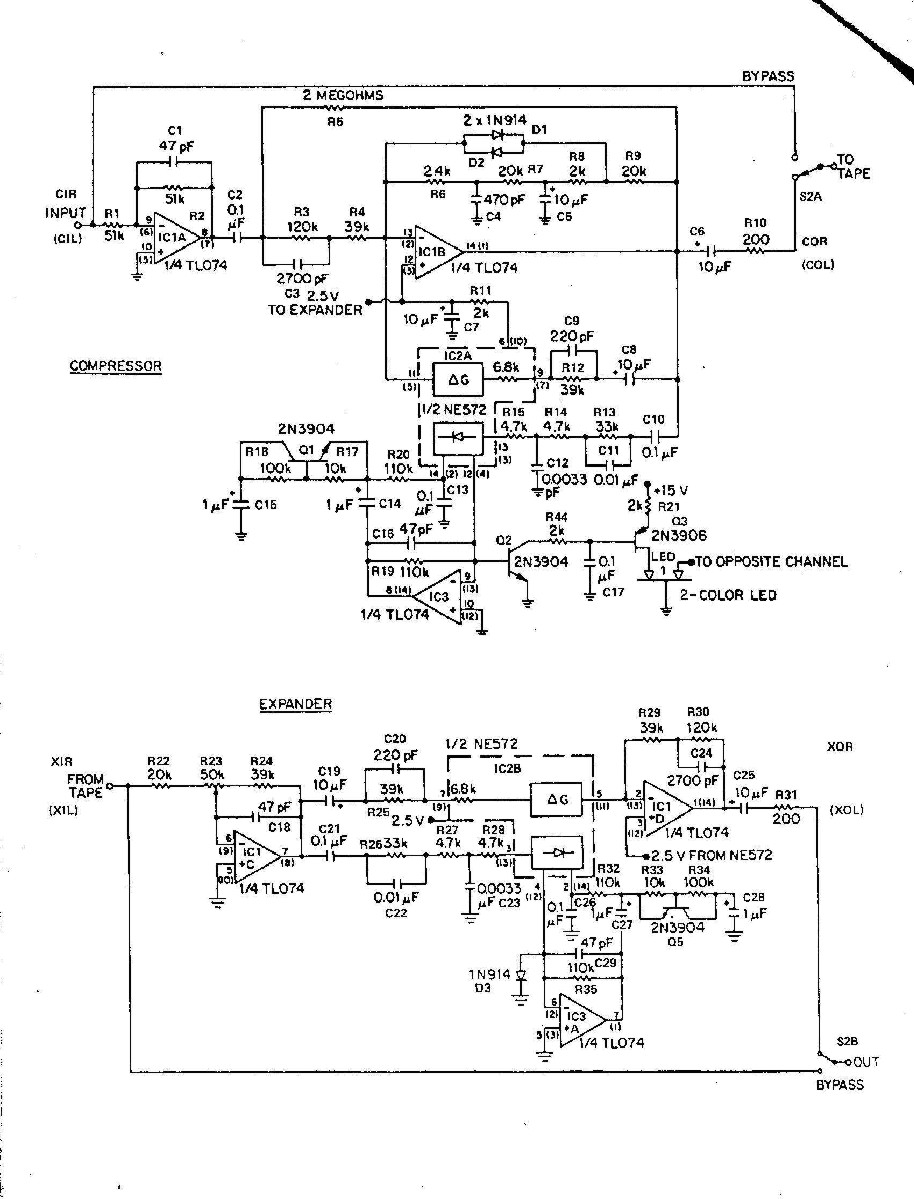
Diodes are also used as the shunt element in a voltage divider.
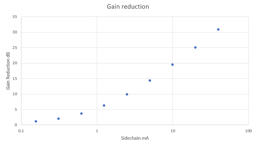
The dynamic resistance of a diode obeys the formula Rd=(1/I)26.10E-3 e.g. at 1mA, the dynamic resistance is 26ohms.
In the 2254, IIRC, there are 4 diodes in bridge, but actually, AC-wise, they are two parallel strings in series. At least that's what it is in the 33609.
 
That makes perfect sense, thanks.

On the 2254 it's a differential path - the two shunt diodes are both following 22k resistors. Using your formula for dynamic resistance you can plot voltage loss based on sidechain current.

3qoX2Ca.png


For 30 dB GR you only need ~40 uA.

Nifty.
 
JohnRoberts said:
====TMI about tape NR you can skip this too =====
We are all (some of us are) aware of DBX and Dolby tape NR, I sold two different Tape NR kits and this is my best later design.

p-522.jpg


This design uses even more tricks than I listed. I have shared this schematic here before so there are more details in the past discussions. To better understand this you might want to look up a NE572 compander chip... that IC contains a fair gain element and two rectifiers per that can be used separately. In fact back in the 80s I used a 572 inside the side chain for a commercial compressor I designed (LOFT-Phoenix Audio Lab).  I just did a search and see somebody new is using the "Phoenix" name for audio products.... the new Phoenix  like the legend arose from the ashes (but somebody else's ashes. )

JR

@JR does this schematic include the pre and de emphasis typically used in dbx semi-pro tape machines such as the 4 and 8 trackers made by the likes of TEAC/TASCAM.

Cheers

ian
 
ruffrecords said:
@JR does this schematic include the pre and de emphasis typically used in dbx semi-pro tape machines such as the 4 and 8 trackers made by the likes of TEAC/TASCAM.

Cheers

ian
Yes that and more tricks...(too many to list).

You will note that the same Pre-de/emphasis is included in the rectifier path so simple tones work.

Of course the rectifier rolls off very HF and very LF to reduce tracking errors.

JR
 
JohnRoberts said:
Yes that and more tricks...(too many to list).

You will note that the same Pre-de/emphasis is included in the rectifier path so simple tones work.

Of course the rectifier rolls off very HF and very LF to reduce tracking errors.

JR

Excellent. I have some old dbx encoded tapes made on a TEAC A3440 quarter inch 4 track that I would like to be able to play. There are a fair number of A3440 tape machines available but all are sans dbx.  So a couple of NE572 chips and some other parts should  give me four channels of decode.

Cheers

Ian
 
ruffrecords said:
Excellent. I have some old dbx encoded tapes made on a TEAC A3440 quarter inch 4 track that I would like to be able to play. There are a fair number of A3440 tape machines available but all are sans dbx.  So a couple of NE572 chips and some other parts should  give me four channels of decode.

Cheers

Ian
A simple 1:2 expandor with -12dB of de-emphasis will get you in the same ball park but maybe not the same seat or even same row.  I never reverse engineered a dBx playback processor but suspect they also used pole and zero of 2 kHz and 500 Hz for playback de-emphasis. 

dBx marketing made a big deal about RMS detection being some secret sauce that made their rectification for playback decoding more accurate with tape media. I am inclined to to call BS on that, but never tried to playback dBx encoded tapes with my design..... BUT a friend of mine (LT sound) made and marketed his own tape NR that he claimed was dBx compatible and sold his apparently successfully for years.

I don't know all the details of his design but recall that he used null testing to match his to the dBx time constants, and I vaguely recall he used a fast attack trick (different than mine) but not a stock 572 circuit.

I expect you can get most of the way there with 1:2 expansion and -12dB de-emphasis (remember to put it in the rectifier path too. ) The ne572 has its own fast attack circuit (smaller capacitor) so you might get acceptable tracking performance (My friend apparently did but with extra design gyrations).   

I am surprised there aren't any old used dBx playback modules floating around in somebody's dust bin, that can be purchased reasonably, and rehabilitated. At a minimum if rolling your own look for an old dBx schematic to match equalization. Time constants may not be as obvious.

Good luck.

JR

PS: My design is not dBx compatible. IMO mine was superior,  8) but the market place was not convinced. In fact after dBx moved their production to Japan, customers could buy assembled dBx units cheaper than my kits cost. Never a winning business plan for a kit business.  :(
 
I've modded more than I can recall of these DX2/4/8's, removing the "secret" dongle that prevented using them on other brands; actually just removing two transistors (per channel) that muted the input when not connected to a Tascam tape machine. Actually, it would have been simpler to force the control line, but that left the transistors in circuit, which was not a problem with Tascam operating level, but introduced significant distortion when operating at +4. Of course I had to recal the units for the increased op. level.
See attached block dgm showing pre-emphasis over pre-emphasis. One on the signal, and once more to the rms detector.
 

Attachments

  • Tascam DXx bmock dgm.jpg
    Tascam DXx bmock dgm.jpg
    77.2 KB · Views: 23
abbey road d enfer said:
I've modded more than I can recall of these DX2/4/8's, removing the "secret" dongle that prevented using them on other brands; actually just removing two transistors (per channel) that muted the input when not connected to a Tascam tape machine. Actually, it would have been simpler to force the control line, but that left the transistors in circuit, which was not a problem with Tascam operating level, but introduced significant distortion when operating at +4. Of course I had to recal the units for the increased op. level.
See attached block dgm showing pre-emphasis over pre-emphasis. One on the signal, and once more to the rms detector.
AFAIK there is no threshold used in the dBx companding NR, but you may need to scale operating levels.

JR

PS: I do not see any attachment
 
abbey road d enfer said:
Done...  ;D
And note the more extreme band limiting of the side chain, so playback response errors do not get expanded too... a good practice when dealing with tape media.

Rolling off frequency extremes in the side chain on the encode side actually generates a little boost that the symmetrical roll off during playback decode neatly cancels.

JR

PS: OK for today's too much information... extreme LF content from warped or uncentered vinyl playback at low music levels could get boosted up disproportionately. Upon playback through tape media the missing LF warp content could cause a phantom modulation from the absent envelope information. One of the too many tricks in tape NR schematic I posted earlier is an adaptive HPF on the encoder. The 0.1uF (film) cap in series with the encoder input, terminated with a 2M resistor to the output of the inverting compressor stage, creates a HPF whose pole frequency changes with compressor gain. For loud signals when compressor gain is low the HPF pole is 20Hz or better, BUT for low signal levels when the compressor is commanding tens of dB gain, this HPF shift higher to effectively squash the warp modulation, that wouldn't print to tape media anyhow...

Note: I have used this same trick on the input to inverting  EQ section, so they will shift the input HPF pole higher when large amounts of bass boost is commanded.
 
Thanks guys for all the very useful info.

The TEAC A3440 I had came with, I think, a DX9 unit. The DX2/4/8 are for Tascam 32, 34 and 38 machines. I am not sure if the reference lvel for the dbx is the same in all cases. The A3440 is certainly a -10dBu machine - I have never had one but I presume the 32 et al are +4 machines.

It has always been my understanding that dbx is intended not to be level sensitive (unlike Dolby) so maybe a DX4 would do me (I think I have one or two in the loft somewhere).

Cheers

Ian
 
Back
Top