Thanks moamps; I understand those additions necessary to make a practical circuit. Right now I am trying to get my head around the fundamental operation, so..
@JR
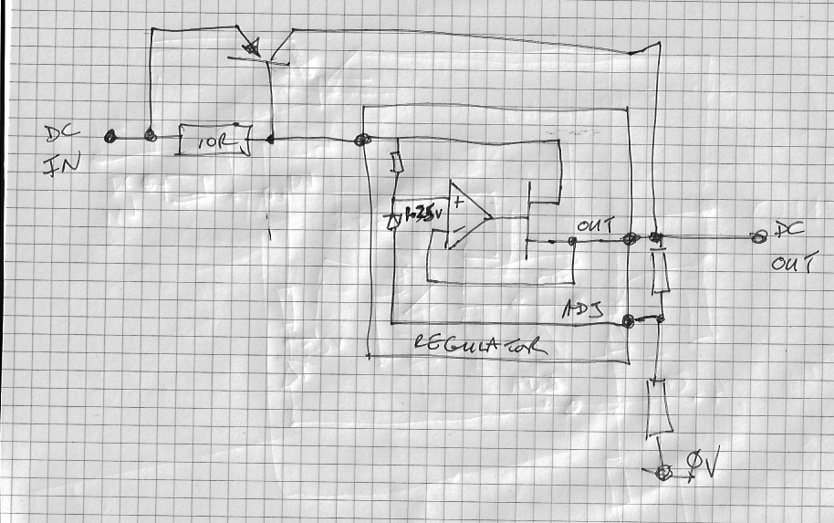
Here is my sketch of a typical adjustable regulator with current boost:
As it says in the data sheets, the regulator works to maintain 1.25 volts across the resistor between the ADJ pin and the OUT pin. You can see the diff amp doing this.
For a light load, the BJT is off and the circuit works like the original three terminal regulator.
If we assume the current out of the ADJ pin is very small compared to the load (which it is) then the current leaving the regulator output pin equals the current going into its input pin. When this current reaches a value large enough to start turning on the BJT, the BJtT starts to supply current to the load. If the load increases, the increase in current from the regulator is sensed by the 10R reissotr, tuens the BJT on some more and provide additional current to the load.
So it seems to me there is a
separate feedback mechanism operating where the the BJT senses the regulator output current independent of the feedback via the diff amp in the regulator.
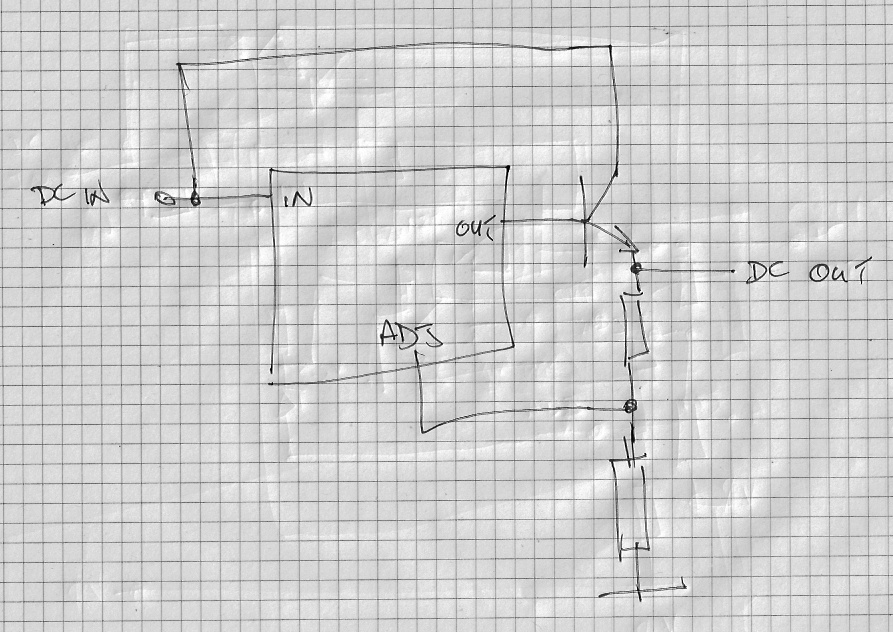
To me, the more obvious topology would have been to use and NPN BJT as an emitter follower so the regulator only has to provide bas current like this:
The regulator raises the NPN base to ensure it is turned on enough to maintain 1.25 across the resistor between the OUT and ADJ terminals and the NPN definitely IS in the feedback loop.
But of course this will not work because with a three terminal regulator we cannot connect the actual supply output to the diff amp input so you have to invent some other method (such as the one in the first pic). To do the emitter follower version you need a four terminal regulator??
Cheers
Ian