


Bo Deadly
Well-known member
This "SQ-OptoGyro" PCB is available on OSHPark for ~$10 USD:
https://oshpark.com/shared_projects/7YbOqXoO
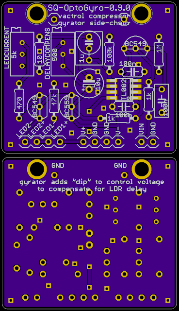
This small 1.5"x1.3" PCB is a vactrol compressor side-chain that implements a soft knee and a gentle compression ratio of about 2.3:1. The marquee feature of this circuit is that it uses a gyrator to add a "dip" or "ripple" to the control voltage to compensate for the time delay of the LDR. It should be possible to retrofit this into any amp that runs on a dual supply and has a vactrol attenuation element such as the RTS Systems 1400 battery powered mic pre.
Note: This is just the side-chain of a compressor. It does not have I/O or a vactrol or anything else. It's just signal in and LED driver.
EXAMPLE:
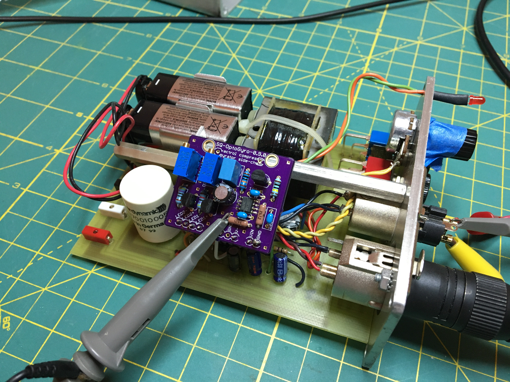
The RTS Systems 1400 is a good candidate for modification which might look like the following:
The following compression "knee" plot is measured values of the stock RTS Systems 1400 stock limiter and two OptoGyro modified units:
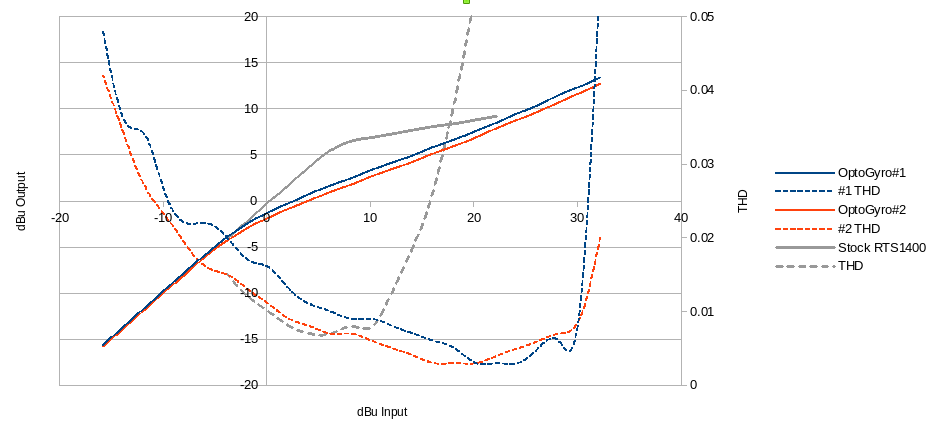
Unlike to the stock RTS Systems 1400 "LIM" circuit, notice how the THD remains low all the way up to the clipping point.
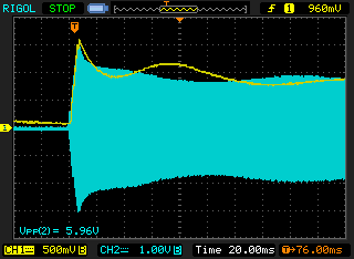
Here is the same circuit showing the resulting waveform with 9.5dB of compression. You can see the effect of the gyrator circuit on the control voltage in yellow:
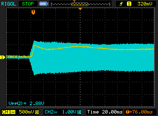
The compensation effect is most dramatic for lower levels of compression such as in this plot for 4.5dB of compression:
Both units in this example used a 2.2K attenuation resistor to ground as described in the ERRATA section and trimmed the DELAYCOMPENS+10R to 330R and trimmed the LEDCURRENT+470 to 2.2K.
PCB BOARD 1.5"x1.3":
THE PROBLEM:
A Light Dependent Resistor (LDR) is slow. When current is applied, it can take 5-10ms for the resistance to drop. When used as a compressor or limiter, the normal feedback loop of signal into the side chain causing attenuation which causes less signal into the sidechain and thus less attenuation ... etc, chances unpredictably. This can cause the output level to swing rapidly in ways that can be audible to the listener.
THE SOLUTION:
The following LTSpice plot illustrates the behavior of this circuit:
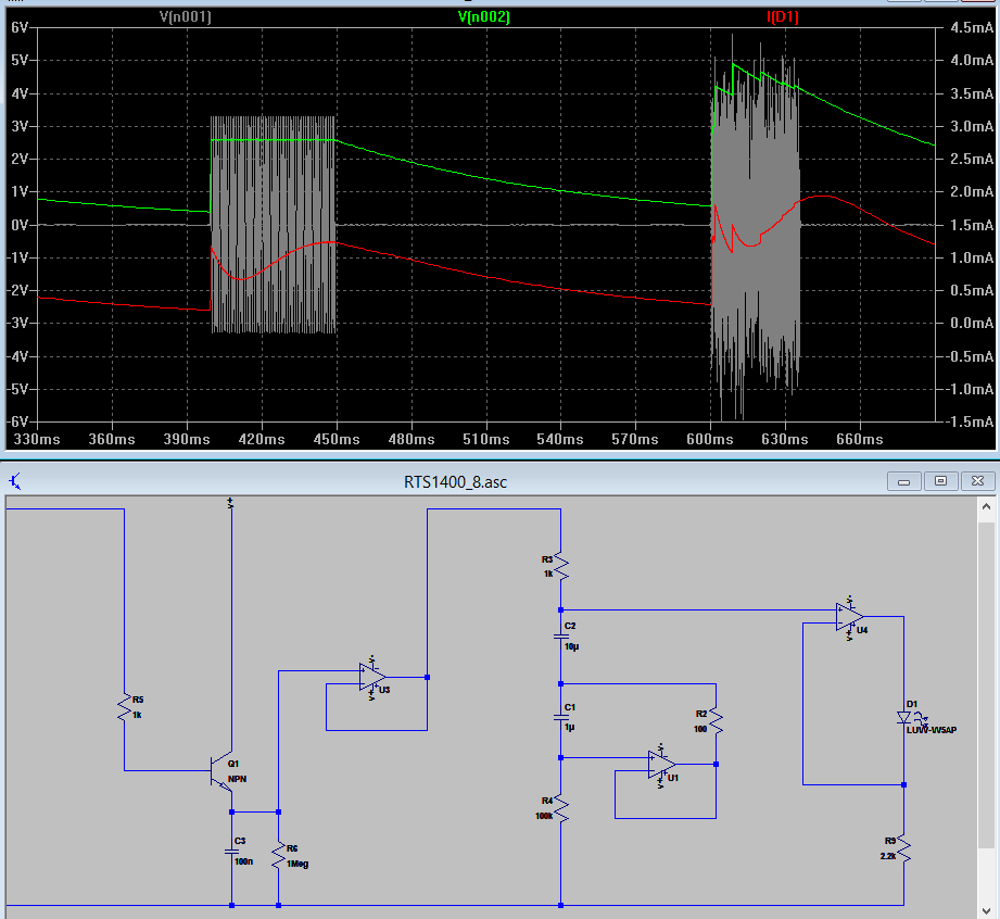
grey: input signal
green: unmodified control voltage (output of first op amp)
red: gyrator modified control voltage (actually LED current which is directly proportional to cv).
You can see how the LED current turns on sharply but then dips before rising back up and settling on the target current. This "ripple" in the LED current compensates for the "ripple" inherent to LDRs.
Observing the LED visually in "SLO-MO" also shows the dip:
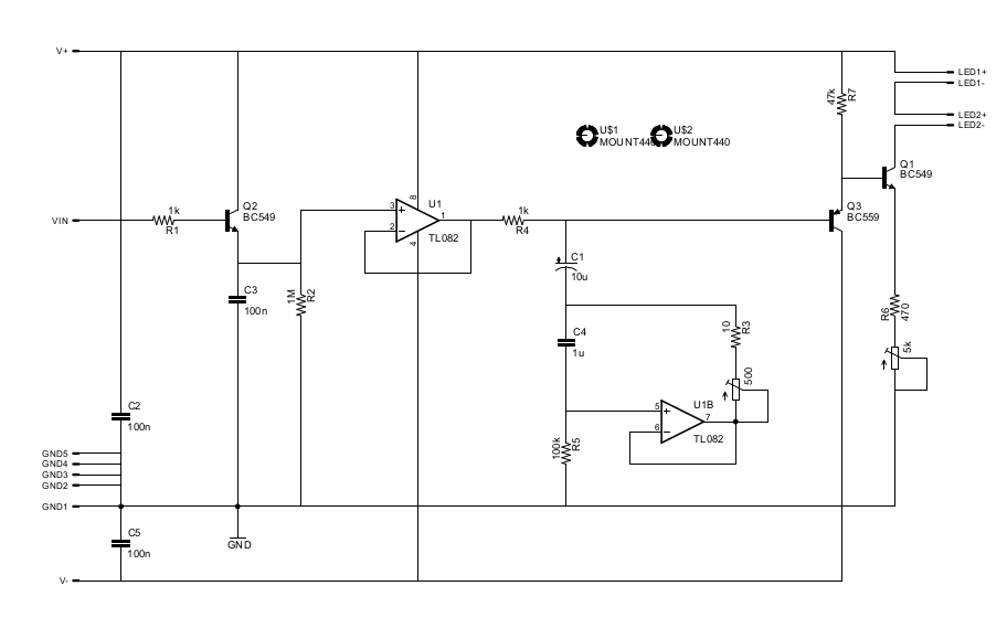
SCHEMATIC:
OPERATION:
All pins labeled GND are the same and refers to signal and power ground.
V+ and V- supplies power such as +-15V or +-9V, etc.
VIN is the signal to sample for controlling the LEDs. Presumably this is supplied by the output of the amplifier with the vactrol element.
LED1+, LED1-, LED2+ and LED2- are the LED of the vactrol and a compression indicator LED. No additional power is consumed by the indicator LED so if there will be no indicator on the panel, it is OK to just wire an LED directly to the board. Or jumper one with some bus wire.
For best results, the delay of the gyrator should be adjusted to match the speed of the specific LDR. Adjust the DELAYCOMPENS trimmer to minimize the ripple in level and THD at a level with moderate compression.
The LEDCURRENT trimmer adjusts the LED current / threshold although this should probably be fixed at something like 2.2K and then use a potentiometer in front of the side-chain to set the threshold.
In practice, for an LDR like the CLM6000 or similarly fast vactrol, DELAYCOMPENS+10R can be replaced with a 330R and the LEDCURRENT+470 can be bypassed with a 2.2K resistor.
See also: https://groupdiy.com/index.php?topic=75165.msg953232#msg953232
ERRATA:
The side chain should be attenuated to adjust the threashold. Otherwise, the threshold will be rather low depending on the LEDCURRENT setting. The threshold can be easily made adjustable by simply adding a potentiometer in front (taking into account that the impedance of the pot will influence the attack). For a fixed threshold, simply add a resistor from the transistor end of R1 to a ground point. For the RTS Systems 1400 examples, I used a 2.2K attenuation resistor and trimmed LEDCURRENT+470 to 2.2K. That makes the threshold ~-2dBu output.
https://oshpark.com/shared_projects/7YbOqXoO
This small 1.5"x1.3" PCB is a vactrol compressor side-chain that implements a soft knee and a gentle compression ratio of about 2.3:1. The marquee feature of this circuit is that it uses a gyrator to add a "dip" or "ripple" to the control voltage to compensate for the time delay of the LDR. It should be possible to retrofit this into any amp that runs on a dual supply and has a vactrol attenuation element such as the RTS Systems 1400 battery powered mic pre.
Note: This is just the side-chain of a compressor. It does not have I/O or a vactrol or anything else. It's just signal in and LED driver.
EXAMPLE:
The RTS Systems 1400 is a good candidate for modification which might look like the following:
The following compression "knee" plot is measured values of the stock RTS Systems 1400 stock limiter and two OptoGyro modified units:
Unlike to the stock RTS Systems 1400 "LIM" circuit, notice how the THD remains low all the way up to the clipping point.
Here is the same circuit showing the resulting waveform with 9.5dB of compression. You can see the effect of the gyrator circuit on the control voltage in yellow:
The compensation effect is most dramatic for lower levels of compression such as in this plot for 4.5dB of compression:
Both units in this example used a 2.2K attenuation resistor to ground as described in the ERRATA section and trimmed the DELAYCOMPENS+10R to 330R and trimmed the LEDCURRENT+470 to 2.2K.
PCB BOARD 1.5"x1.3":
THE PROBLEM:
A Light Dependent Resistor (LDR) is slow. When current is applied, it can take 5-10ms for the resistance to drop. When used as a compressor or limiter, the normal feedback loop of signal into the side chain causing attenuation which causes less signal into the sidechain and thus less attenuation ... etc, chances unpredictably. This can cause the output level to swing rapidly in ways that can be audible to the listener.
THE SOLUTION:
The following LTSpice plot illustrates the behavior of this circuit:
grey: input signal
green: unmodified control voltage (output of first op amp)
red: gyrator modified control voltage (actually LED current which is directly proportional to cv).
You can see how the LED current turns on sharply but then dips before rising back up and settling on the target current. This "ripple" in the LED current compensates for the "ripple" inherent to LDRs.
Observing the LED visually in "SLO-MO" also shows the dip:
SCHEMATIC:
OPERATION:
All pins labeled GND are the same and refers to signal and power ground.
V+ and V- supplies power such as +-15V or +-9V, etc.
VIN is the signal to sample for controlling the LEDs. Presumably this is supplied by the output of the amplifier with the vactrol element.
LED1+, LED1-, LED2+ and LED2- are the LED of the vactrol and a compression indicator LED. No additional power is consumed by the indicator LED so if there will be no indicator on the panel, it is OK to just wire an LED directly to the board. Or jumper one with some bus wire.
For best results, the delay of the gyrator should be adjusted to match the speed of the specific LDR. Adjust the DELAYCOMPENS trimmer to minimize the ripple in level and THD at a level with moderate compression.
The LEDCURRENT trimmer adjusts the LED current / threshold although this should probably be fixed at something like 2.2K and then use a potentiometer in front of the side-chain to set the threshold.
In practice, for an LDR like the CLM6000 or similarly fast vactrol, DELAYCOMPENS+10R can be replaced with a 330R and the LEDCURRENT+470 can be bypassed with a 2.2K resistor.
See also: https://groupdiy.com/index.php?topic=75165.msg953232#msg953232
ERRATA:
The side chain should be attenuated to adjust the threashold. Otherwise, the threshold will be rather low depending on the LEDCURRENT setting. The threshold can be easily made adjustable by simply adding a potentiometer in front (taking into account that the impedance of the pot will influence the attack). For a fixed threshold, simply add a resistor from the transistor end of R1 to a ground point. For the RTS Systems 1400 examples, I used a 2.2K attenuation resistor and trimmed LEDCURRENT+470 to 2.2K. That makes the threshold ~-2dBu output.