AudioIngenia
Well-known member
- Joined
- Feb 22, 2017
- Messages
- 68
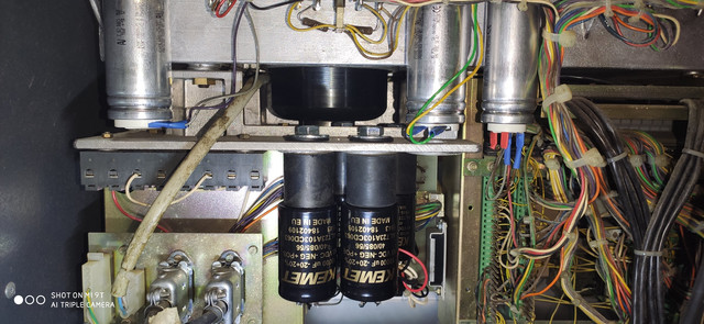
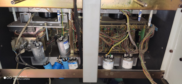
I have rescued this Studer A80 from an old recording studio.
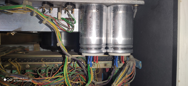
Someone replaced the big capacitors. The fastening is difficult, they are longer than the original ones and do not have screw to fix.
I am considering replacing again.
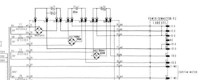
In the service manuals, I don't see all of these condensers ....
I await expert advice ...
Someone replaced the big capacitors. The fastening is difficult, they are longer than the original ones and do not have screw to fix.
I am considering replacing again.
In the service manuals, I don't see all of these condensers ....
I await expert advice ...