Signal bus to aca

GroupDIY Audio Forum

Help Support GroupDIY Audio Forum:

This site may earn a commission from merchant affiliate links, including eBay, Amazon, and others.

boji

Well-known member
Joined
Jan 6, 2010
Messages
2,376
Location
Maryland, USA
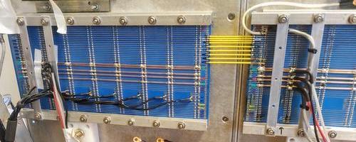
May I ask for opinions on the below method of getting aux/groups bused down to aca's?

Thought of keeping signal on an uninterrupted core seems...clean, convenient.
However, if bridging the cards at each end using FEP ribbon cable seems the wiser move, would you mind saying why? 

Thank you!
TZd9mic.jpg


Edit: Forgot to mention layout includes null (guard?) traces interleaved between signal, so plenty of room for extra wire.
 
many various console manufactures use ribbons for such a purpose.  the current trident consoles have head bucket motherboard with IDC connections on each end and the ribbon together so all the buckets eventually reach the amps for bus out, aux out, multi-track assignments, etc and then out. in fact the whole board is basically ribbon cables joining the sections together. so for example, the input jacks are all on their own PCB that is mounted and ribbons into the mother board.  the channels connect to the motherboard using  the same connectors found in Neve  V series desks, I think they are mitsubishi connectors., then the motherboard ribbon together to make the buss. it's quite clean and makes for easy servicing.
 
Thanks for the input gents.  IDC would have the advantage to making disconnection easier if it were ever needed.

I suppose I have a superstitious belief adding IDC contacts between backplanes would create slightly more resistance than using straight wire.
 
There are probably millions of successful ribbon cable bus connections,,, Of course a quick web search will turn up the notable ribbon cable problems (Hint: search "Mackie ribbon cable problem", but they are not the only company to ever have problems.

At Peavey we had our own machine and tooling. As I recall we had at least one production issue when the tooling got out of adjustment, but we caught it before they got out into the world.

It is a good technology, but nothing is 100% perfect.

JR 

 
boji said:
I suppose I have a superstitious belief adding IDC contacts between backplanes would create slightly more resistance than using straight wire.
Not superstitious because it's actually true. Does it matter, though?
Each IDC contact adds about 10milliohms. A bucket of 8 modules gives a bus resistance of about 150millohms (length 12", width 40mil, 1oz), half of it for 2oz copper. This is to be compared with the bus impedance of the bucket, that's about 1kohm.
It may introduce second-order effects with very long bus running at very low impedance.
Only once I faced an issue with ribbon cable in bus. It was a 36 ch Soundcraft 6000, that the customer complain about intermittent clicks; of course when I was there it never happened! After a long time of unfruitful investigations, I decided to replace the ribbon cable, which solved the problem. The post-mortem revealed traces of oxydation on the copper cable.
 
abbey road d enfer said:
Not superstitious because it's actually true. Does it matter, though?
Each IDC contact adds about 10milliohms. A bucket of 8 modules gives a bus resistance of about 150millohms (length 12", width 40mil, 1oz), half of it for 2oz copper. This is to be compared with the bus impedance of the bucket, that's about 1kohm.
It may introduce second-order effects with very long bus running at very low impedance.
Only once I faced an issue with ribbon cable in bus. It was a 36 ch Soundcraft 6000, that the customer complain about intermittent clicks; of course when I was there it never happened! After a long time of unfruitful investigations, I decided to replace the ribbon cable, which solved the problem. The post-mortem revealed traces of oxydation on the copper cable.
It is an all too common practice to repair intermittent (corroded) IDC connections by soldering. When properly manufactured, IDC connections are gas tight and robust, of course there are always examples of failures with millions of connections out in the world, but 99.999.....% are good.

JR
 
JohnRoberts said:
It is an all too common practice to repair intermittent (corroded) IDC connections by soldering. When properly manufactured, IDC connections are gas tight and robust, of course there are always examples of failures with millions of connections out in the world, but 99.999.....% are good.

JR
I was unlucky enough to deal with the 0.0001%  ;D
 
abbey road d enfer said:
I was unlucky enough to deal with the 0.0001%  ;D
I was lucky enough to dodge that one bullet (we caught it in house), but have a list of other such problems we typically encounter in mass production.

Do not be afraid to use IDC...

JR
 
JohnRoberts said:
I was lucky enough to dodge that one bullet (we caught it in house), but have a list of other such problems we typically encounter in mass production.

Do not be afraid to use IDC...

JR
Was not afraid. Soon back in the saddle. Used a lot of those without any issue.
 
the only IDC issue I ever had was when they were handmade and people were not paying attention making a bad idc cable.  orientation of the header is very important. 
 
abbey road d enfer said:
Was not afraid. Soon back in the saddle. Used a lot of those without any issue.
I know you get it, I didn't want to scare the young'uns as we share our failure experiences from dealing with millions of parts..

JR
 
Decided to go manual...  Thanks anyway for the IDC-trusting stories!
dJ4y82B.jpg


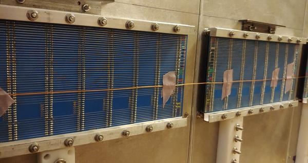
May I ask another question to double check the rationale on agnd runs?

I believe it's best to run each unbalanced mono subgroup TP with reference direct off the backplane bus (closest to channel ref), but is there any disadvantage to tie to busbar?  (Feel like I asked this question before and folks said to get as close to PCB outputs as possible)...

 
boji said:
Decided to go manual...  Thanks anyway for the IDC-trusting stories!
dJ4y82B.jpg


May I ask another question to double check the rationale on agnd runs?

I believe it's best to run each unbalanced mono subgroup TP with reference direct off the backplane bus (closest to channel ref), but is there any disadvantage to tie to busbar?  (Feel like I asked this question before and folks said to get as close to PCB outputs as possible)...
I feel like I should understand the terminology but sadly I don't get a clear picture of what you are asking (perhaps provide a link to your schematic).

For a one off design you can experimentally see if an approach works, or maybe try a couple and compare them.

JR
 
I did switch gears late last night...
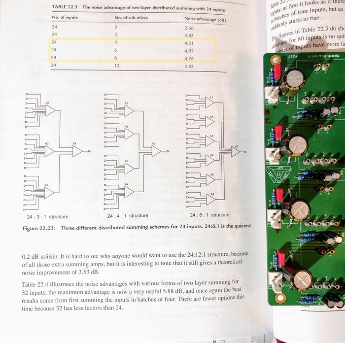
Channel's unbalanced mix outs are grouped in sets of 4 for optimal noise reduction, sent to inverting aca, so just want to make sure I'm feeding com from channel subgrp output side at the best point.    Thanks for input!
NgJYlNw.jpg


Edit: Experimentation might prove useful, but if I have to turn these joined buckets from a seated home position up onto a plywood sheet one more time... ;D
 
boji said:
I did switch gears late last night...
Channel's unbalanced mix outs are grouped in sets of 4 for optimal noise reduction, sent to inverting aca, so just want to make sure I'm feeding com from channel output side > aca input side at the best point.    Thanks for advice.
NgJYlNw.jpg


Edit: Experimentation might prove useful, but if I have to turn this frame on its side from a home position one more time... ;D
I understand you have not done provison for ground-sensing resistors, so the non-inverting input of the ACA of each bucket of 4 should be referenced at a point situated in the middle of the bucket. Then these should be connected to the non-inverting imput of the final ACA via wires of equal resistance. Brute-force ground samplinfg.
 
I understand you have not done provision for ground-sensing resistors
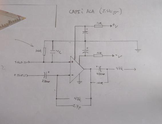
I'd rather not reprint Jeff's aca schema without permission however reviewing the schematic,  the positive pin of the inverted summing amp, received as 'shield', is split and sent to 100k resistor with a .01uf cap in parallel, then to agnd.

so the non-inverting input of the ACA of each bucket of 4 should be referenced at a point situated in the middle of the bucket.

Does this still apply given the 100k above? Thank you.
 
boji said:
I'd rather not reprint Jeff's aca schema without permission however reviewing the schematic,  the positive pin of the inverted summing amp, received as 'shield', is split and sent to 100k resistor with a .01uf cap in parallel, then to agnd.
Which agnd? Draw a sketch please.
 
Thanks Abby, guess I should say the PGND's agnd  ::)

Confused by the fact the schema's input signal label says shield... perhaps there's nothing to worry about.

WSI5ihx.jpg
 
I think some people are still angry with me about the last time I broached the issue of distributed summing. I will try to be kinder and gentler and say nothing this time....

In an ideal world (my ideal world) the sum bus is operating differentially (i.e. referencing the channel local audio 0V to the master section audio 0V.)

Note: I didn't mention ground once.

JR
 

Latest posts

Back
Top