Any drawback with connecting Relay coil between V+ and V-

GroupDIY Audio Forum

Help Support GroupDIY Audio Forum:

This site may earn a commission from merchant affiliate links, including eBay, Amazon, and others.

elskardio

Well-known member
Joined
Sep 29, 2010
Messages
572
Location
Montreal - Canada
Hi Guys,

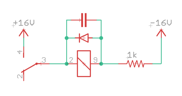
Is there any drawback to connect a relay's coil between V+ and V-, instead of V+ and Ground?

Example for a 24V relay using a split 16v power supply.

relay.png


Thanks
 
No worries. In fact, it's much better than dumping that current into audio ground. Just make sure the current is right.

Another trick is to use a larger resistor with a cap across it so that you get a moment of high current but then it drops to staying current level. That will be easier on the supply and on the relay.
 
elskardio said:
With the 1k resistor, I measure 23.8V across the relay’s coil... I’m i missing something here?

Per your measurements, 1K seems like the proper value for THAT relay in order to drop the rail voltages down to 24 VDC.  A different relay coil will likely require a different series resistor.  Ohms Law calculations.....

Bri
 
elskardio said:
With the 1k resistor, I measure 23.8V across the relay’s coil... I’m i missing something here?

Cutting it fine ???
Remember that a 'X Volt' relay will operate some volts below X .
Check datasheet - but it seems you could  drop a few more volts for margin.
I'm assuming a standard relay. Not sure from memory about reed relays but I think similar applies.
 
A 7.5 or 8.2V Zener diode instead of the 1K resistor would be a better option because it would prevent coil resistance from affecting coil terminal voltage.

I think you'll also find that if the resistor is removed that it will be quieter at turn on if there is no capacitor across the coil. The peak current at turn-on is much higher with the capacitor in the circuit.
 
elskardio said:
With the 1k resistor, I measure 23.8V across the relay’s coil... I’m i missing something here?
Relays require more pull-in current to first actuate, then continuous hold current to remain on after actuated.

So an optimal series resistor for continuous duty might be larger to drop that hold voltage even lower.  A common old relay trick (already shared) is to use two series resistors, with a cap shunting across one. This can deliver a full 24V at initial turn on, then as the capacitor charges up the voltage relaxes to the more modest hold voltage.

For a simple one relay design this may be over engineering complexity, but be aware of old these school tricks to save current in larger designs if needed.

JR 
 
JohnRoberts said:
Relays require more pull-in current to first actuate, then continuous hold current to remain on after actuated.

So an optimal series resistor for continuous duty might be larger to drop that hold voltage even lower.  A common old relay trick (already shared) is to use two series resistors, with a cap shunting across one. This can deliver a full 24V at initial turn on, then as the capacitor charges up the voltage relaxes to the more modest hold voltage.

For a simple one relay design this may be over engineering complexity, but be aware of old these school tricks to save current in larger designs if needed.

JR
Yeah, nowadays with SMPS being what they are that trick is pretty much a waste of parts. And in practice the cap needs to be electrolytic so it also wastes space and needs to be eventually replaced. Not sure why I mentioned it. Just being pedantic I guess.
 
Just substitute a 7.5 or 8.2V Zener for the 1K resistor in your original drawing which places the Zener in series with the coil.

Zener cathode points to the coil. Zener anode to -16V.
 
This is how I would do it.
Because my main concern is injecting noise into the rails. And the relay won't suffer if it receives a short 32V kick. You need to select the cap for making the kick adequate in length.
You may want to add a snubber across the switch, or not.
 

Attachments

  • relay.jpg
    relay.jpg
    35.3 KB · Views: 11

Latest posts

Back
Top