That should work.
Here's basically what you need to do:
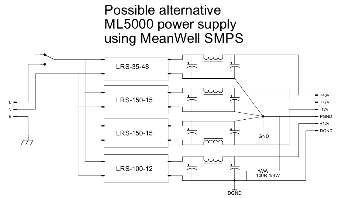
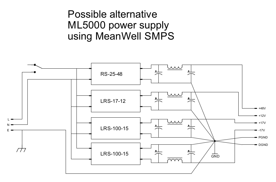
So at earth there is a FAT wire to the chassis. Then, also from the earth terminal, a FAT wire to the "star" ground. In practice the "star" ground should just be a PCB ground plane so that each ground wire connected to it is surrounded by ground plane. So there are no "traces". It's all just ground pour. You can also pour it on top and add vias to stitch them together. If you're not making a PCB, you could use a small piece of bus bar from an electrical supply store.
A few details are:
1) Use a hefty power switch to handle the surge currents of the SMPS. I'm not sure if a common 20A toggle is enough. Check the datasheets. Maybe an SPDT doubled up makes 40A? Or maybe there's some sort of "circuit breaker" type of switch that doubles as a power switch? Note that you probably cannot solder the terminals because they'll be so big. You might have to crimp some spades and get a switch with screw terminals.
2) Use fat wire for everything connected to LNE. Maybe 8 or 6 AWG? Again, your iron might not be able to solder that such as the earth wire to the ground plane for example in which case you might need to crimp a spade and screw it down somehow. Or use a bus bar.
3) Capacitors need to be rated for voltage of course but they don't have to be as big as they are in a linear supply (and should not be because SMPS sometimes don't like that). They just need to be big enough to get the high frequency ripple. The best way to check would be to just load test one and look at the ripple with a scope.
4) Inductors should be the largest inductance you can find at the necessary current. So search Mouser for something rated at 100% higher. So at 14A, the inductance is going to only be so high. Maybe 10uH or something like that. Above that, you're taking tube amp chokes for $100. But again, the inductance only needs to be enough to get close to 20kHz with the cap that follows.
Post picks of the enclosure. Presumably you're just going to recycle the exisiting one with the connector and mains in an such? Maybe reuse the power switch?
Does the exisiting supply work at all? If yes, and you have a way to measure current (measure voltage across resistors and use ohms law), it would be nice to know how much the console is really drawing. An old supply is probably not nearly as efficient as the new MW supplies so it's probably over-rated and it's not pulling anywhere near 7A per rail. But it would be good to know what it really is. The 12V line will probably vary greatly depending on how many relays and LEDs are engaged at any particular moment.
I'm sure I'm leaving out something important but if you post pics and part numbers other people will chime in with good ideas.