Meanwell Modules - AH ML5000 PSU Replacement

GroupDIY Audio Forum

Help Support GroupDIY Audio Forum:

This site may earn a commission from merchant affiliate links, including eBay, Amazon, and others.
squarewave said:
Hi Blissy,

You don't need heat sink pours for the smaller transistors. They should be thermally coupled to the larger transistors which are also handling literally 100x the power of the small ones. So do like I said before and just put them on top. You should create a nice collector pour for them but maybe only 1/4 of the area of one of the larger transistors.

Ah ok got it sorry misunderstood! will fix up Thanks

So is there solderable copper exposed to the tab of the large transistors? Or are you just going to bolt them in? I would make that a plated hole so so that you can get a really good thermal bond with a bunch of solder. Otherwise, if you use a bolt, you might need some thermal paste or something like that which I always thought was messy.

Will add

Also, it now occurs to me that the big speech I made about all-things-ground converging at the same point is being thwarted by this separate board. This board is now providing the "star" ground point. So you really need to move all of those spades over the the center of the board. Even if it means bending a wires from the middle of this board to an offset location of the other. Then make a ground pour down the middle, above and below stitched with vias and get all of the spade terminals and caps close together.

Ok I thought this might be the case, So just to confirm do you mean all of the Negatives of the Modules as well ? (conx2,3,6) or just all the AGND spade connectors need conform to the centre of the new PCB and a single wire will connect the New PCB to the old one ?

Connector 2,6 and Conx14 from the old PCB need to all move to the middle of the via stitched GND of the CM board with a wire snaking from Conx6 down to the old PCB. 

Where the 3 wires (+17,-17 and AGND) all come off the board, where it goes out AND where it comes in from the other board, the wires need to be close together. The rule is that you want return currents in close physical proximity to source currents. We talk about that all the time here. It's very important. If you have a gap between the wires, it will emit electromagnetic radiation that will be picked up by nearby amplifiers. So you have to move those spades over.

Thanks Squarewave I hope my post makes sense!
 
It looks like you have 3 spade terminals in the upper right that are pos, gnd and neg. Just shift those all down so that  you have everything positive in the upper half, everything ground in the middle and everything negative in the lower half.
 
squarewave said:
It looks like you have 3 spade terminals in the upper right that are pos, gnd and neg. Just shift those all down so that  you have everything positive in the upper half, everything ground in the middle and everything negative in the lower half.

Ok so I have moved the Connectors, fixed the pours and added the exposed copper for the tab of pass transistor. I have also added connectors to pass thru the +48 Volts as this PCB will cover the connector below making it difficult to connect the spade lugs.

I double checked the 48V Phantom to triple check for any noise and I discovered a rather high pitched Buzz that seems to change with load, how disappointing :( 
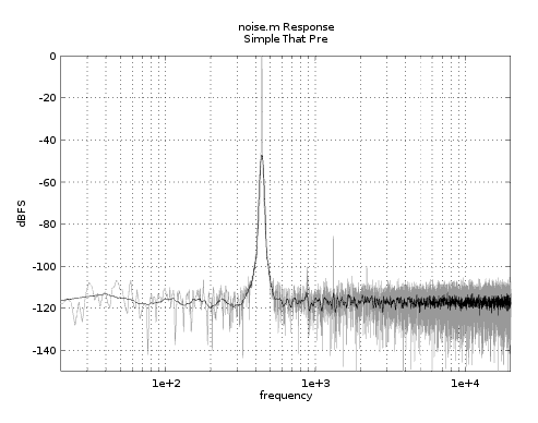
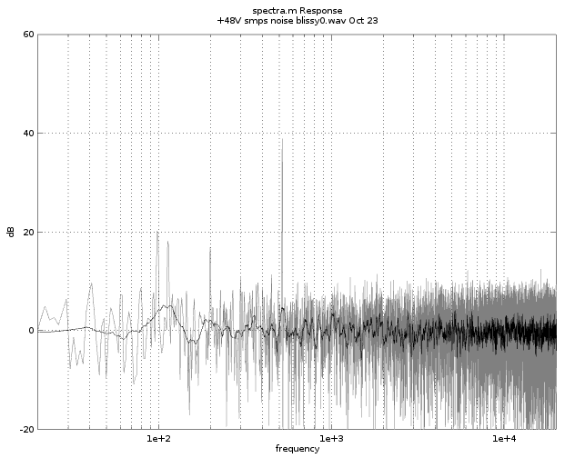
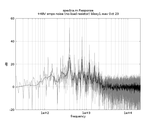
I checked it with and without the current filter PCB and it is filtering.. just not low enough. Could I implement a basic RC Filter on the the 48V Rail as is low current Looking at JLMs website he uses a SMPS for phantom, He recommends a 10R and 470uF cap. this would take me down to 33hz

Actually it might be better to just change the inductor on the original PCB. I could get a 10mh inductor that will and replace the 100uf cap with a 470uf which will take me down to around 50hz this would be easier and cleaner?

https://drive.google.com/drive/folders/1T99iWEIkpcDTJIBi-PSlBwC9T0iKvNX2?usp=sharing
 
That would probably work fine but there's there is a gap between conx4 5 and 6 which like I said before isn't good. It's probably not big enough to be a problem but is there any reason why all of the terminals cannot be together? Also, there's no need for the ground plane to widen like that. I would adjust conx{4,5,6} so that they line up vertically. Then make the ground plane width the same all the way across.

Also, the "+48 THRU" is also creating a gap between the supply and it's return wire so again you have a problem with the return follows supply rule. And it's just chewing up heat sinking area. Can you not just connect the +48 to the other board?

Regarding your 48V buzz, that is a little discouraging because you already have 47uH + 100uF filtering with a 2kHz corner so I have to wonder why you have buzzing going around or below that range. Are you listening to a mic pre from the console using the old supply or the new supply that you know has some mains noise or just directly using some other method?

Note that depending on how much current is being drawn, your phantom could loose a few volts even with 10R. For example, if you have all 32 channels of phantom and each draws about 10mA, that's 0.32A * 10 ohms = 3.2V lost. Meaning your 48V becomes 44.8V. You could replace that 47u inductor with something like a 1mH inductor. But that's going to be a chunker through hole part so maybe add it somehow (maybe to your new board) to make another 1mH / 1000uF LC filter which gets down to ~160Hz and has a DCR of only 1R so you're voltage drop at 0.32A becomes only 320mV.
 
squarewave said:
That would probably work fine but there's there is a gap between conx4 5 and 6 which like I said before isn't good. It's probably not big enough to be a problem but is there any reason why all of the terminals cannot be together? Also, there's no need for the ground plane to widen like that. I would adjust conx{4,5,6} so that they line up vertically. Then make the ground plane width the same all the way across.

Will do, Thanks!

Also, the "+48 THRU" is also creating a gap between the supply and it's return wire so again you have a problem with the return follows supply rule. And it's just chewing up heat sinking area. Can you not just connect the +48 to the other board?


Regarding your 48V buzz, that is a little discouraging because you already have 47uH + 100uF filtering with a 2kHz corner so I have to wonder why you have buzzing going around or below that range. Are you listening to a mic pre from the console using the old supply or the new supply that you know has some mains noise or just directly using some other method?

Yes listening to a Console Mic pre, using the new supply the noise is present on all channels I have tested so far. The noise is not present on any channel when using the old supply.   


Note that depending on how much current is being drawn, your phantom could loose a few volts even with 10R. For example, if you have all 32 channels of phantom and each draws about 10mA, that's 0.32A * 10 ohms = 3.2V lost. Meaning your 48V becomes 44.8V. You could replace that 47u inductor with something like a 1mH inductor. But that's going to be a chunker through hole part so maybe add it somehow (maybe to your new board) to make another 1mH / 1000uF LC filter which gets down to ~160Hz and has a DCR of only 1R so you're voltage drop at 0.32A becomes only 320mV.

Having a look I can probably get a 1mH inductor that I could fit on the Old PCB or even mount it off the board and possibly get an even larger one. To avoid taking up space and creating return issues on the +48v Rail?
 
Blissy said:
Having a look I can probably get a 1mH inductor that I could fit on the Old PCB or even mount it off the board and possibly get an even larger one. To avoid taking up space and creating return issues on the +48v Rail?
Pay attention to current requirements. A 1mH inductor that handles the right current will almost certainly not fit on the SMD pad of the existing 47uH inductor. A 1mH inductor that can handle 1A is a chunky part. Probably the size of a large cap.

As long as you follow the return follows supply rule you should be fine with return currents. So if you really had to booger something, you could literally zip-tie an axial inductor to a 1000uF capacitor with two wires in one end and two wires out the other  and put some heavy shrink tube around that and as long as the wires in are close together and the wires out are close together you shouldn't have any significant gaps.

Not that I recommend you do that. That would be a little ugly but it's better to see a POC work now than make new boards. It's not common for a build to come right out the first time. If you get a POC working then you can think about a revision to make things pretty inside (but if it works ...).
 
squarewave said:
Pay attention to current requirements. A 1mH inductor that handles the right current will almost certainly not fit on the SMD pad of the existing 47uH inductor. A 1mH inductor that can handle 1A is a chunky part. Probably the size of a large cap.

As long as you follow the return follows supply rule you should be fine with return currents. So if you really had to booger something, you could literally zip-tie an axial inductor to a 1000uF capacitor with two wires in one end and two wires out the other  and put some heavy shrink tube around that and as long as the wires in are close together and the wires out are close together you shouldn't have any significant gaps.

Not that I recommend you do that. That would be a little ugly but it's better to see a POC work now than make new boards. It's not common for a build to come right out the first time. If you get a POC working then you can think about a revision to make things pretty inside (but if it works ...).

Thanks Squarewave, just did some further testing I bodged in a 160hz RC filter just to see the results. I know it is only a first order filter, however the noise was still present at very high gains with an unterminated Microphone input. With a Microphone plugged in and normal gain levels (about 40 -50db) the noise is not noticeable. Which I suppose is all that matters, especially once I have the 2nd order LC filter

I have updated the CM PCB to include a LC Filter with space for a 1mh Axial Inductor and 1000uf Cap with out effecting the rest of the PCB too much. I think...
I have tried to remedy any return follows supply issues, which I believe I have.

https://drive.google.com/drive/folders/1T99iWEIkpcDTJIBi-PSlBwC9T0iKvNX2?usp=sharing
 
Actually I think I know what the high-pitched whine is. It's in "hiccup" mode because it's not loaded. How much current is being drawn by the desk 48V? If it's below 300mA or so, the 1.6A supply will throttle the output which will cause mid-frequency (2k-ish) noise. Try adding a 100 ohm 50W resistor across the 48V output. Or maybe it could be 25W if you only test it for 60 seconds or so. I bet that's it.

And I really hope it is because, after thinking about it a little more, you can't put 1000uF on the output anyway. It will trigger protection mode and won't start up.

If you don't have 100R, maybe as big as 500 might be enough to pull it out of hiccup mode. If you have like 4 10W 1K for example, in parallel that would be a good load too. Use ohms law ...

Now if that fixes the problem, I'm not sure what the best course of action is long term because it's a real drag to burn 25W on a load resistor. The entire rest of the circuit probably doesn't dissipate that much.
 
squarewave said:
Actually I think I know what the high-pitched whine is. It's in "hiccup" mode because it's not loaded. How much current is being drawn by the desk 48V? If it's below 300mA or so, the 1.6A supply will throttle the output which will cause mid-frequency (2k-ish) noise. Try adding a 100 ohm 50W resistor across the 48V output. Or maybe it could be 25W if you only test it for 60 seconds or so. I bet that's it.

And I really hope it is because, after thinking about it a little more, you can't put 1000uF on the output anyway. It will trigger protection mode and won't start up.

If you don't have 100R, maybe as big as 500 might be enough to pull it out of hiccup mode. If you have like 4 10W 1K for example, in parallel that would be a good load too. Use ohms law ...

Now if that fixes the problem, I'm not sure what the best course of action is long term because it's a real drag to burn 25W on a load resistor. The entire rest of the circuit probably doesn't dissipate that much.

Great Idea ! So I picked up a couple of high watt Resistors started with 100ohm and the noise instantly reduced considerably!! I increased the resistance in increments to see how high I could get away with. Using a 1K 5watt resistor archives the the same noise reduction as the 100ohm and only at 2.3watts. Still gets considerably hot however I could get a 10w resistor.

There is still some noise when the input is unterminated and everything is at max (60db of gain Masters at full)
to be Safe I could keep the second LC filter on the new PCB and change the 1000uf Cap to a 470uf which gives a conner freq of 230hz. 
 
So if you use the old supply and leave the input unterminated you don't hear the noise? Typically when you measure the noise performance of a device, you set the source impedance to a realistic value. Most microphones would not present a source impedance of more than a few hundred ohms. So leaving it unterminated is not a typical test. But if the old supply is quiet in that scenario, it's not an insignificant result.

Is there any way you can get a proper spectrum of this noise?

If you can record the noise to a wav file with a decent USB audio interface and post it in your folder I can generate a high-res plot like this:

stp.png


This is actually of a 440Hz reference tone playing through the DUT to establish the 0dBFS point but you can skip the ref tone. If you make a stereo wav 96kHz 32 bit float file with 10 seconds of recording on the right channel, I should be able to feed it straight into my script without any extra work. Then I can post the plot here and you'll "see" exactly what noise your hearing.

Incidentally, that plot is of a MeanWell APC-16-350 SMPS with CMs powering a THAT 1510 / THAT 1646 circuit and you can see that there's zero mains feed-through. But that's a little 350mA SMPS.

Anyways, I'm not sure the LC filter is going to be the right move. The inductor is also soaking up power on start up as well and 470u doesn't get you down to mains frequencies and an unshielded high value inductor might pickup noise just by itself, and and an.... ech.

So, unless the noise measurements turn up better news, I think you should consider just doing another CM and not goof around troubleshooting 42 different circuits. And because the power isn't that much less (1/10th the current but 3x the voltage equates to only about half the power) you might as well just use the same circuit and transistors as the +17 CM. You can make the area of the board for +48 CM half the size of the other +-17 ones.

Or, and I know this hurts, but you could just make another board. It sounds like you need some place to put fat load resistor anyway. But 1K is only 3% of the power of that particular SMPS. The problem is that SMPS is too big. Maybe try to find a smaller one? They're cheap so just getting a new one is probably cheaper than throwing bigger parts at the one you have. Otherwise, I would do more like 470R maybe. You could use a 15-20W 470R a resistor like Bourns PWR263S-20-4700J or something surface mount knowing that you have a good amount of board to make a collector-pours-stitched-with-vias heat sink. Or you could just do what most people would probably do and use a cheap ceramic thing.
 
squarewave said:
So if you use the old supply and leave the input unterminated you don't hear the noise? Typically when you measure the noise performance of a device, you set the source impedance to a realistic value. Most microphones would not present a source impedance of more than a few hundred ohms. So leaving it unterminated is not a typical test. But if the old supply is quiet in that scenario, it's not an insignificant result.

Correct using the old supply with an unterminated input there is no noise.

Is there any way you can get a proper spectrum of this noise?

If you can record the noise to a wav file with a decent USB audio interface and post it in your folder I can generate a high-res plot like this:

stp.png


This is actually of a 440Hz reference tone playing through the DUT to establish the 0dBFS point but you can skip the ref tone. If you make a stereo wav 96kHz 32 bit float file with 10 seconds of recording on the right channel, I should be able to feed it straight into my script without any extra work. Then I can post the plot here and you'll "see" exactly what noise your hearing.

Shall do!! Thankyou ever so much ! will Upload ASAP. better to record the direct out or do you mean the RIGHT Bus output. Microphone unterminated? Gain high /fader level? I Assume everything at 0 

Incidentally, that plot is of a MeanWell APC-16-350 SMPS with CMs powering a THAT 1510 / THAT 1646 circuit and you can see that there's zero mains feed-through. But that's a little 350mA SMPS.

Anyways, I'm not sure the LC filter is going to be the right move. The inductor is also soaking up power on start up as well and 470u doesn't get you down to mains frequencies and an unshielded high value inductor might pickup noise just by itself, and and an.... ech.

So, unless the noise measurements turn up better news, I think you should consider just doing another CM and not goof around troubleshooting 42 different circuits. And because the power isn't that much less (1/10th the current but 3x the voltage equates to only about half the power) you might as well just use the same circuit and transistors as the +17 CM. You can make the area of the board for +48 CM half the size of the other +-17 ones.

agreed!


Or, and I know this hurts, but you could just make another board. It sounds like you need some place to put fat load resistor anyway. But 1K is only 3% of the power of that particular SMPS. The problem is that SMPS is too big. Maybe try to find a smaller one? They're cheap so just getting a new one is probably cheaper than throwing bigger parts at the one you have. Otherwise, I would do more like 470R maybe. You could use a 15-20W 470R a resistor like Bourns PWR263S-20-4700J or something surface mount knowing that you have a good amount of board to make a collector-pours-stitched-with-vias heat sink. Or you could just do what most people would probably do and use a cheap ceramic thing.

are you suggesting scraping both boards and doing one entirely new one? or adding a third? or adding the power resistor to the new CM Board.
So the current SMPS module is the RS-25-48 which is only rated at 570ma. I could drop down to the RS-15-48 at 330ma.
 
better to record the direct out or do you mean the RIGHT Bus output. Microphone unterminated? Gain high /fader level? I Assume everything at 0
Do mic terminated with 150 ohms if you can. I realize the offending scenario is with unterminated but if there's no noise when terminated then doing unterminated isn't really that useful. At least this way we'll see what the noise is in a realistic scenario. Set mic gain to max, turn off low cut, send the direct out to your USB interface and then record 10 seconds of silence. Then in your DAW export that track to the right channel of a stereo wav file. Left track will be ignored but I suppose you will need to put something there just to export a stereo file so maybe just copy the same track or whatver.

are you suggesting scraping both boards and doing one entirely new one? or adding a third? or adding the power resistor to the new CM Board.
I'm suggesting you add a third PCB for just the 48V CM and 48V load resistor of sufficent size to keep it out of hiccup mode. Presumably you're just going to stack all of the boards with standoffs which, for purposes of heat dissipation is actually a pretty good way to do it anyway.

So the current SMPS module is the RS-25-48 which is only rated at 570ma. I could drop down to the RS-15-48 at 330ma.
Oh, I thought it was 1.6A. No, RS-25-48 is perfect. And you can trim up to get over the diode drops of the CM. So a 1K resistor is probably fine then and it only needs to be 5-10W which is much better.
 
squarewave said:
Do mic terminated with 150 ohms if you can. I realize the offending scenario is with unterminated but if there's no noise when terminated then doing unterminated isn't really that useful. At least this way we'll see what the noise is in a realistic scenario. Set mic gain to max, turn off low cut, send the direct out to your USB interface and then record 10 seconds of silence. Then in your DAW export that track to the right channel of a stereo wav file. Left track will be ignored but I suppose you will need to put something there just to export a stereo file so maybe just copy the same track or whatver.

Ok here is the 96khz Wav. Test conditions were 140ohm across pin 2,3 Gain @ 60db MAX Channel fader at 0. Direct out feeding a line input on my Tascam ML32-D convertor at 96k. Let me know if any adjustments are required I really appreciate this :)

obviously there is still some Mains feed through from the +17 / -17 rails the new board has not been manufactured however the phantom noise far over shadows that.

https://drive.google.com/file/d/1lXC4LdqIEFEL1fYXnJZ3zPObwMiHwh4j/view?usp=sharing


I'm suggesting you add a third PCB for just the 48V CM and 48V load resistor of sufficent size to keep it out of hiccup mode. Presumably you're just going to stack all of the boards with standoffs which, for purposes of heat dissipation is actually a pretty good way to do it anyway.

Ah ok got it ! correct one more won't hurt :)

Oh, I thought it was 1.6A. No, RS-25-48 is perfect. And you can trim up to get over the diode drops of the CM. So a 1K resistor is probably fine then and it only needs to be 5-10W which is much better.

Great
 
Ok here is the 96khz Wav. Test conditions were 140ohm across pin 2,3 Gain @ 60db MAX Channel fader at 0. Direct out feeding a line input on my Tascam ML32-D convertor at 96k. Let me know if any adjustments are required I really appreciate this :)

obviously there is still some Mains feed through from the +17 / -17 rails the new board has not been manufactured however the phantom noise far over shadows that.
Well the news is not great. Here's the result (noise floor adjusted to "0 dB"):

blissy0.png


There a pretty serious component at 522 Hz that's about 25 dB above the noise floor. I have to wonder if it's still in hiccup mode. Maybe do another one without the load resistor so that we can confirm that there is actually a major difference.

The mains peaks are not too bad at ~10dB above at 100, 114 and 200. A 1K / 100u CM should knock those down >20dB.

You'll definitely need a CM for the 48V. A 1K / 100u CM would knock that down >30dB at 522 Hz.

But I must say I'm not impressed with these SMPS. I have never seen this from the little beige plastic enclosed LED supply ones. Maybe the LED ones are actually quieter. I think you can make this work with another CM. But for future reference, the next person doing this should try something other than LRS and RS series.
 
squarewave said:
Well the news is not great. Here's the result (noise floor adjusted to "0 dB"):

blissy0.png


There a pretty serious component at 522 Hz that's about 25 dB above the noise floor. I have to wonder if it's still in hiccup mode. Maybe do another one without the load resistor so that we can confirm that there is actually a major difference.

The mains peaks are not too bad at ~10dB above at 100, 114 and 200. A 1K / 100u CM should knock those down >20dB.

You'll definitely need a CM for the 48V. A 1K / 100u CM would knock that down >30dB at 522 Hz.

But I must say I'm not impressed with these SMPS. I have never seen this from the little beige plastic enclosed LED supply ones. Maybe the LED ones are actually quieter. I think you can make this work with another CM. But for future reference, the next person doing this should try something other than LRS and RS series.

Thanks SquareWave, here is a sample without the load resistor on the 48v supply. much louder

https://drive.google.com/file/d/1R5yUDnFev90ooX4Ao3tcpKY1QZ9lbaXw/view?usp=sharing 

Good news regarding mains peaks! getting closer :)

Yes a bit disappointed especially the 48v being so low current. However hopefully will be all worth it! have learnt a great deal doing this so worth wild already.

I shall get to work on a 48v CM board tomorrow... its 3AM in Australia..
 
Thanks SquareWave, here is a sample without the load resistor on the 48v supply. much louder
Indeed. Hiccup mode is a disaster with that SMPS so clearly with the load resistor it is getting pulled out of hiccup mode:

blissy1.png


Fortunately because of the modular build, you could always get other SMPS if you have to. Like I said, I know the beige plastic enclosure LED supplies are quiet. So you could always get an APC-25-500 for example (or maybe you need APC-E for 220VAC in AU?) for a whopping $12 USD. So don't get discouraged. Just do the 48V CM / load resistor board and if it's still not good enough you can look at swapping in other SMPS without doing anything to your boards.
 
squarewave said:
Indeed. Hiccup mode is a disaster with that SMPS so clearly with the load resistor it is getting pulled out of hiccup mode:

blissy1.png


Fortunately because of the modular build, you could always get other SMPS if you have to. Like I said, I know the beige plastic enclosure LED supplies are quiet. So you could always get an APC-25-500 for example (or maybe you need APC-E for 220VAC in AU?) for a whopping $12 USD. So don't get discouraged. Just do the 48V CM / load resistor board and if it's still not good enough you can look at swapping in other SMPS without doing anything to your boards.

Wow! good to know that resistor is doing its job!

So I modified both the CM board PCB for the +17/-17 and created a new phantom CM Board
the phantom CM board is probably overkill size wise but for stacking purposes its easier. the 1k load resistor is;
https://au.element14.com/bourns/pwr263s-35-1001f/res-1k-1-35w-power/dp/2101653

Any feedback apricated!

https://drive.google.com/drive/folders/1T99iWEIkpcDTJIBi-PSlBwC9T0iKvNX2?usp=sharing

Cheers
Blissy 
 
I haven't calculated power of the CM vs the resistor but I think they're probably about the same in which case I would be inclined to devote about an equal amount of area for each. Right now it looks like the CM area is a lot smaller than the resistor. Is that on purpose? Did you figure on more power from the resistor? I suppose that's possible.

Is there a pad for the other pin of that resistor? I'm not familiar with your layout software so it's not obvious. Also, it looks like you know this, but, unlike the transistors, it does not look like the tab of that resistor is actually connected to anything. So it's ok (and good) that you have it soldered to ground.

So if the +48V board is smaller, obviously at least two of the bolt holes are not going to line up with the +-17 board and I assume you know how the whole thing is going to bolt together. Meaning I'm wondering why you don't just make them both the same size and then use those standoffs that are a female at one and and male at the other and just stack the +-17 board on top of the new +48 V board.

Incidentally you'll probably want to put the +-17 board on top since it's dissipating more power.

If you have not already done so, I would give all 100u cap footprints enough clearance and use the larger most common pitch for that that size cap so that you could choose to put a bigger cap in their. One nice side effect of the CM is that because the cap charges through the 1K, it won't stress the SMPS on startup causing it to go into protection and fail to start. So it's actually OK to use a bigger cap there if you want as long as it doesn't make the rails reach their resting voltages too slowly.

Finally, I know I said to keep the terminals that are supply current next to the terminals that are returning that current next to each other but if you need room just to getting them on and off, use your judgement about how far apart they need to be. It's sometimes hard to judge size from these computer generated layouts. If you think they're too close together, it's not a problem if they're 2cm aprart vs 1cm.
 
squarewave said:
I haven't calculated power of the CM vs the resistor but I think they're probably about the same in which case I would be inclined to devote about an equal amount of area for each. Right now it looks like the CM area is a lot smaller than the resistor. Is that on purpose? Did you figure on more power from the resistor? I suppose that's possible.

That was my original thought that the resistor may generate more heat. However it's probably safer to allow for equal space. I shall revise this.

Is there a pad for the other pin of that resistor? I'm not familiar with your layout software so it's not obvious. Also, it looks like you know this, but, unlike the transistors, it does not look like the tab of that resistor is actually connected to anything. So it's ok (and good) that you have it soldered to ground.

The other Pad for the resistor is going to the ground plane making it hard to see


So if the +48V board is smaller, obviously at least two of the bolt holes are not going to line up with the +-17 board and I assume you know how the whole thing is going to bolt together. Meaning I'm wondering why you don't just make them both the same size and then use those standoffs that are a female at one and and male at the other and just stack the +-17 board on top of the new +48 V board.

This is a good point! They should all be the same size. The only issue is Lining up the original filter PCB and the new +/- 17v CM PCB. As on the original the +17 AGND -17 output connectors are offset to the top Right. So I will have to use wire to snake it to the centre of the new CM board. I could use short spade terminal links.

Incidentally you'll probably want to put the +-17 board on top since it's dissipating more power.

Will do!

If you have not already done so, I would give all 100u cap footprints enough clearance and use the larger most common pitch for that that size cap so that you could choose to put a bigger cap in their. One nice side effect of the CM is that because the cap charges through the 1K, it won't stress the SMPS on startup causing it to go into protection and fail to start. So it's actually OK to use a bigger cap there if you want as long as it doesn't make the rails reach their resting voltages too slowly.

Yes Definitely, Pretty sure I have but will double check. May even include a duel pin spacing footprint.

Finally, I know I said to keep the terminals that are supply current next to the terminals that are returning that current next to each other but if you need room just to getting them on and off, use your judgement about how far apart they need to be. It's sometimes hard to judge size from these computer generated layouts. If you think they're too close together, it's not a problem if they're 2cm aprart vs 1cm.

Thanks Again!
Cheers Blissy
 
squarewave said:
I haven't calculated power of the CM vs the resistor but I think they're probably about the same in which case I would be inclined to devote about an equal amount of area for each. Right now it looks like the CM area is a lot smaller than the resistor. Is that on purpose? Did you figure on more power from the resistor? I suppose that's possible.

Is there a pad for the other pin of that resistor? I'm not familiar with your layout software so it's not obvious. Also, it looks like you know this, but, unlike the transistors, it does not look like the tab of that resistor is actually connected to anything. So it's ok (and good) that you have it soldered to ground.

So if the +48V board is smaller, obviously at least two of the bolt holes are not going to line up with the +-17 board and I assume you know how the whole thing is going to bolt together. Meaning I'm wondering why you don't just make them both the same size and then use those standoffs that are a female at one and and male at the other and just stack the +-17 board on top of the new +48 V board.

Incidentally you'll probably want to put the +-17 board on top since it's dissipating more power.

If you have not already done so, I would give all 100u cap footprints enough clearance and use the larger most common pitch for that that size cap so that you could choose to put a bigger cap in their. One nice side effect of the CM is that because the cap charges through the 1K, it won't stress the SMPS on startup causing it to go into protection and fail to start. So it's actually OK to use a bigger cap there if you want as long as it doesn't make the rails reach their resting voltages too slowly.

Finally, I know I said to keep the terminals that are supply current next to the terminals that are returning that current next to each other but if you need room just to getting them on and off, use your judgement about how far apart they need to be. It's sometimes hard to judge size from these computer generated layouts. If you think they're too close together, it's not a problem if they're 2cm aprart vs 1cm.

Ok I have updated the two new PCB's (+/-17v CM PCB and Phantom CM PCB) They are now all the same size to make it easy for stacking.

On the phantom board the spacing is now equal. CM vs Resistor. I have also added an alternative resistor package/footprint for safety as well as updating the capacitor footprint size. 

Made some minor adjustments to the +/-17 board. 

Any feedback welcome

https://drive.google.com/drive/folders/1T99iWEIkpcDTJIBi-PSlBwC9T0iKvNX2?usp=sharing

Cheers Blissy
 
Back
Top