AudioIngenia
Well-known member
- Joined
- Feb 22, 2017
- Messages
- 68
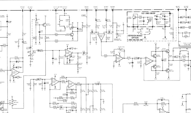
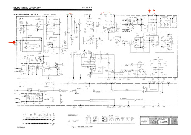
I'm testing the summing fader module of a Studer 980 mixer in a Calrec S2 sidecar.
I get the sound on the output, it seems that the sound is correct.
See attached image. I don't like the bridge on the postfader insert.
It is an unbalanced output to balanced input. How can I modify that? Any suggestion?
I get the sound on the output, it seems that the sound is correct.
See attached image. I don't like the bridge on the postfader insert.
It is an unbalanced output to balanced input. How can I modify that? Any suggestion?