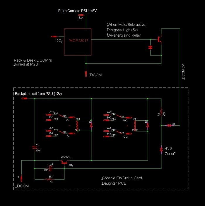
Actually I was wrong about the direction of current in my previous description. I see that your relay transistors are current sinks and not current sources. Of course the direction of current doesn't matter but because I'm not sure I understand the identifiers you're using to describe your circuit, I will just restate my concern:
If the current used to power relays is not supplied by conductors physically adjacent to the conductors sinking that current, then the "source follows sink" rule is not satisfied. And because all 8 of the conductors in what appear to be RJ45 jacks are occupied by current sinking conductors, the only conductor in that cable bundle that could supply the source current would have to be the cable shield. Meaning unless the cable shield is supplying the 12V used to power the relays (and it most certainly should not), then it must be coming from somewhere else and that is not ideal. But again, it's not a show stopper because the caps on the transistor bases will limit the intensity of the magnetic fields generated when a relay switches on.


")