PCB trouble

GroupDIY Audio Forum

Help Support GroupDIY Audio Forum:

This site may earn a commission from merchant affiliate links, including eBay, Amazon, and others.

Holger

Well-known member
GDIY Supporter
Joined
Jun 11, 2006
Messages
893
Location
Hamburg, Germany
I'be built two D-AOCs in 2008 which I use often. One was dead, so I opened it and found the B+ up to 330V. I've suspected the regulator and exchanged the 783, still weird voltages. I unmounted the PCB and found this:
daocres.jpg

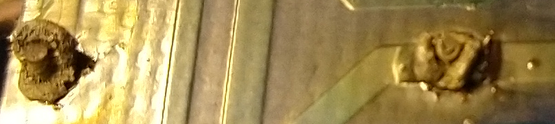
These are the solder joints of the first 2W 470R resistor after the rectifier diodes. It seems that all the current flowing through this (and certainly the associated heat) stressed the solder points and the PCB traces. Repaired, compressor is working again now.
 
If this 270R feeds another smoothing cap then at power up, since the charge on the cap is zero, the volts across it is zero. At this instant the resistor has to sustain the full HT voltage so there is a peak current flow through the resistor which can momentarily cause it to exceed its power rating. In practice it can take several mains cycles for the cap to charge up so I now routinely fit 5W rated resistors in this position for this reason.

Cheers

Ian
 
I´ve seen that a lot in medicre designed gear (sorry Holger  ;) ) where thermal layout has not been done right. Often power resistors and Zeners unsolder themselves because the heat development is so high, that it corrupts the solder. ATM I have a KRK monitor on the bench which has an intermittantly working poweramp. In the PSU there´s a pair of Zeners which get really hot. The PCB around them is browned and they unsolder themselves. I´ve installed new ones, same type but with long legs to get the heat out of the diode but have enough surface to dissipate the heat before it enters the PCB.
Another example for the same problem is the TAC Matchless channel mute circuit which dims the switch illumination.
 
where thermal layout has not been done right.

I have 5 Tannoy System 8 NFM monitors and I have had to repair 3 of them for this exact reason. The +15v reg gets really hot and the legs desolder themselves from the board. I am modding the other 2 to resolve this issue before it happens.... They are only 5 years old and otherwise in good shape.

Peter
 
I wonder if 2021's gonna be the year I finally get to overhaul my Tannoy Precision 6D's electronics (replacing the hot regulators and amps, and the dicky switches, with some classD amps and small DSP's)...


peterc said:
I have 5 Tannoy System 8 NFM monitors and I have had to repair 3 of them for this exact reason. The +15v reg gets really hot and the legs desolder themselves from the board. I am modding the other 2 to resolve this issue before it happens.... They are only 5 years old and otherwise in good shape.

Peter
 
jensenmann said:
I´ve seen that a lot in medicre designed gear (sorry Holger  ;) ) where thermal layout has not been done right. Often power resistors and Zeners unsolder themselves because the heat development is so high, that it corrupts the solder. ATM I have a KRK monitor on the bench which has an intermittantly working poweramp. In the PSU there´s a pair of Zeners which get really hot. The PCB around them is browned and they unsolder themselves. I´ve installed new ones, same type but with long legs to get the heat out of the diode but have enough surface to dissipate the heat before it enters the PCB.
Another example for the same problem is the TAC Matchless channel mute circuit which dims the switch illumination.
+1

Elevated temperature over time can cause solder joints to crystalize and lose mechanical strength. I have seen this most often on 3 terminal regulators that are hard to kill, but when inadequately heat sunk can degrade solder connections. Such solder connections will look dull, not shiny. Not sure about lead free solder that starts out looking dull.  ::)

JR

 
Back
Top