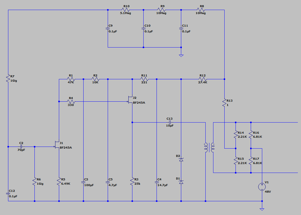
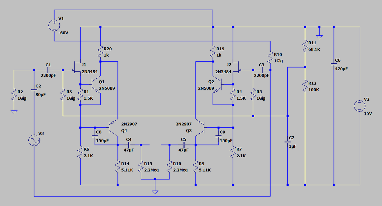
Bored with all the common microphone circuits?

GroupDIY Audio Forum

Help Support GroupDIY Audio Forum:

This site may earn a commission from merchant affiliate links, including eBay, Amazon, and others.
Gus said:
Some Sterling/groove tubes solid state microphone use a 200 ohm series resistor after an emitter follower before the transformer.

The 200 ohm resistor is for better phase linearity at both ends of the spectrum, it also extends the HF response. These microphones handle high SPL with no problem. Edcor nickel core 1:5 tranny connected backwards of course gets the job done. Only one cap in the audio path and polypropylene. No electrolytics are used anywhere.
 
Khron said:
Pretty sure C12 is unnecessary there. And/or R7.

Well, that's unless you enjoy the 8-9 minutes of "warm-up time" that the circuitry would need, for the capsule bias voltage to reach maximum... ::)

(1 gig and 100nF give a time constant of 100 seconds to reach 63%, and about 5 times as long to reach maximum. And that's not even counting the time constant of the filtering before that...)

OK, I deleted a few components for a time constant of 4 seconds to 90%. It's a little noisier now and SPL capability went down somewhat. I'm afraid I won't be doing this mod to the other one though. Sometimes nonesense actually sounds good, lol
 
analag said:
The 200 ohm resistor is for better phase linearity at both ends of the spectrum, it also extends the HF response.
Since it is a minimum phase circuit, the phase response is a corollary of the frequency response.
I would be more concerned withfrequency response than phase response.
Putting a resistor in series with a transformer dampens the two usual peaks, one that is the result of the nominal primary inductance and the coupling capacitor, the other the result of the joint effects of leakage inductance and parasitic capacitance.
It does not extend the HF response, it makes it flatter.
 
abbey road d enfer said:
Since it is a minimum phase circuit, the phase response is a corollary of the frequency response.
I would be more concerned withfrequency response than phase response.
Putting a resistor in series with a transformer dampens the two usual peaks, one that is the result of the nominal primary inductance and the coupling capacitor, the other the result of the joint effects of leakage inductance and parasitic capacitance.
It does not extend the HF response, it makes it flatter.

OK
 
rogs said:
I must admit I've been a bit disappointed that some of the more experienced experimenters on this board didn't find the RF project we discussed here: https://groupdiy.com/index.php?topic=71586.0  interesting enough to take any further?

I did enjoy reading through that.  I have a number of MKH here, and they are really great.  I can barely keep up with existing repair work as-is......
 
rogs said:
Looking at the posts on this board over the last year or so, and it seems that there is LOTS of interest in various versions of old tube mic 'clone' projects .. which do tend to be about the same old circuits, IMHO... 
I have already expressed concerns about it. Many think that GroupDIY's only purpose is to help clone vintage equipment, which it is not. I encourage submitting new experiments.
I'm not a mic builder, because I think the most significant improvements involve skills and equipment that are out of reach for me, like micro-machining.
Indeed your RF mic project is great, and very well documented, but I believe the thing that is missing for it to become a hit is a dedicated specific capsule, and that's the real hard part...
 
abbey road d enfer said:
......but I believe the thing that is missing for it to become a hit is a dedicated specific capsule, and that's the real hard part...
It would be nice to find a low tension, 'push pull' SDC capsule - like the Sennheiser MKH types  - that I wouldn't need to arrange a mortgage to buy! :)  Not likely though...

This type of project is more suited to low tension capsules - understandably -- but AFAIK membrane tension is never quoted in the spec of cheap Chinese capsules?

The published 'specs' for most of the cheap K.67 and K.47 Chinese copies seem to be largely just made up numbers from the marketing guys.....
 
analag said:
mikk.png

Here is the schematic of two of my working solid state mikes. One is edge terminate and the other is center terminated capsule. C2 is the capsule, R13 is omitted.

Set R4 to 10meg and run the sim again. Think K67
 
Gus said:
Set R4 to 10meg and run the sim again.
I'm not willing to re-create the .asc file, but I believe it would result in significant drop of the HF response, which may be what you're after, but seems uncontrollable since it depends on the FET's input capacitance.
It would also add significant noise.
 
I posted 10meg because it would show the LPF. I posted that because you need to be mindful of source resistance before a follower.
 
analag said:
mikk.png

Here is the schematic of two of my working solid state mikes. One is edge terminate and the other is center terminated capsule. C2 is the capsule, R13 is omitted.

I think this would be a better first project than a tube microphone. Search for the Brauner Phantom C thread here for why.
 
Gus said:
I think this would be a better first project than a tube microphone. Search for the Brauner Phantom C thread here for why.

Perhaps, but.....

Khron said:
Pretty sure C12 is unnecessary there. And/or R7.

Well, that's unless you enjoy the 8-9 minutes of "warm-up time" that the circuitry would need, for the capsule bias voltage to reach maximum... ::)

(1 gig and 100nF give a time constant of 100 seconds to reach 63%, and about 5 times as long to reach maximum. And that's not even counting the time constant of the filtering before that...)
 
Khron

I understand your point however, I think people should experiment. If they read the thread they can try different things

I have set long time constants on the RC capsule voltage as well as shorter.
It is only Rs and Cs to learn what this does.

Experiment with circuits sometimes it is only Rs and Cs

To much just building a kit/clone crap here.

I wonder if that is what drove others that posted interesting things about microphone design left.


Latest posts

Back
Top