Trident A Range Low Freq Response

GroupDIY Audio Forum

Help Support GroupDIY Audio Forum:

This site may earn a commission from merchant affiliate links, including eBay, Amazon, and others.

Lerok

Active member
Joined
Jan 17, 2018
Messages
37
Location
Fort Wayne, Indiana
Hello, recently I've been messing around in LTSpice with the Trident A Range Preamp schematic mostly out of curiosity (I know it's quite similar to the Helios schematic I just ordered PCBs for, and having tracked most of my teenage years on an 80b, I've fallen in love with the trident sound) - anyways, the more I play with the schematic, the more "meh" it seems due to it's lackluster low frequency response.

At maximum gain, I'm simulating somewhere around a 15dB drop around and below 1k - was this a common 'feature' of the A range? Or am I missing something...

I removed the voltage divider on the input as I didn't see much use for it, but here's what I'm messing with now:
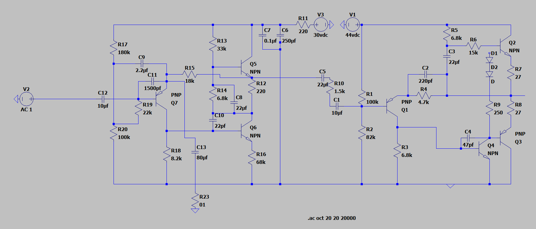
GPBhnz7.png


Anyways, seems like a fun small project after I get my helios pres up and running! I suppose now is as good a time as any to ask - has anyone had much success? A brief forum search yielded very few people tackling the trident pre, though I wonder if that's more due to it's relative obscurity (compared to neve/ssl/api/etc) or the lack of solid documentation...

Thanks, as always!
 
The only problem with LF response I see here is the combination of 80uF and 1 ohm for C13 and R23, resulting in a -3dB point at 2kHz! This is what detremines dominantly the LF response.
Certainly these are not the correct values in operation.
If I can rely on a schematic, the minimum value of this resistor is 110r, which results in a -3dB point @18hz, which, although not impressive, is certainly acceptable in the context of everything being high-passed at 40Hz, that is typical in pop.
 
I am, pretty sure R16 at 68K is wrong. And C9 at 2.2uF seems very off to me.

As Abbey says the 1R resistor in series with the 80uF cap sets the gain. You are unlikely to obtain more that 40dB of closed loop gain from this three transistor circuit. Since the closed loop gain is close o the 18K resistor divided by the resistor in series with the 80uF then the minimum value I would expect for this resistor is 180 ohms.

Cheers

Ian
 
ruffrecords said:
I am, pretty sure R16 at 68K is wrong. And C9 at 2.2uF seems very off to me.
R16 is definitely off, although it may not show much in the sim, since the load is very light. According to the schemo in our Technical Documents, it is a 68 ohm.
C9 may be OK, since it is used to bootstrap R13.
 
compare component values in question with the Revox A77 input circuit,
from which the A range preamp was derived.
 

Attachments

  • A77_pre.jpg
    A77_pre.jpg
    295.3 KB
Interesting. I had not realised the similarities between the two designs. Possibly a little bit naughty.

I still don't grok the cap from the first emitter to the dc bias network. I cannot work out how it might bootstrap the second stage collector load.

But anyway, the source of the LF problem is clear.

Cheers

Ian
 
ruffrecords said:
I still don't grok the cap from the first emitter to the dc bias network.
This one bootstraps the bias network of the 1st transistor, which increases its input Z.
The Trident 1038 seems to have it (schemo almost illegible) but the 2038 does not.

I cannot work out how it might bootstrap the second stage collector load.
The cap from the collector of the 2nd transistor (bottom) bootstraps the bias network of the 3rd (top) transistor, which not only increases the impedance seen by the collector but also increases the capability of delivering positive peaks. In other words, it produces a CCS load (at AC) to the bottom transistor.
 
I was assuming I could in practice push the preamp to around 40dB (similar to the helios 2128), and even at 1 ohm, the gain was only hitting around 37dB (thus my weird value for r23). Increasing that to a more 'real world' practical number such as 100 ohms and switching the value of r16 from 68k to 68 (dangers of copying schematics at 2am, haha) has completely fixed the issue! Seems to be pushing out around 43dB with a common 1.5dB drop below 100hz now!

Interesting notes on the cap present in the 1038 vs the 2038 - I will have to try both.

Anyways, a huge thank you for the extra set of eyes, I should have double checked myself before submitting a thread here - now I can get on to the fun part! I'm thinking a 1:10 input transformer for around 20dB of gain shoud be appropriate, and I have them readily available from my helios pres - I'm planning on finishing up the schematic this week and adding the common accoutrements found on modern preamps (pad, polarity, 48v), and am madly switching between a transformerless output or out xfmr from crimson. I'll try transformerless first and see how it sounds, in the interest of saving money for a broke college kid.

Once again thanks, and I'll update this thread with the finished schemo as soon as I get that done!
 
Lerok said:
I'm thinking a 1:10 input transformer for around 20dB of gain should be appropriate,
I'm not so sure. You should check the collector current of the first transistor. It's easy to measure; take the voltage across the 18k feedback resistor and divide by 18 000.
I have a feeling the voltage is about 4V, which would indicate a collector current of about 200uA, which in turn would put the OSI (Optimum Source Impedance) around 2k, and thus would suggest a 1:3 or 1:4 xfmr.
Anyway, who needs 60 dB of gain?  :)
 
abbey road d enfer said:
I'm not so sure. You should check the collector current of the first transistor. It's easy to measure; take the voltage across the 18k feedback resistor and divide by 18 000.
I have a feeling the voltage is about 4V, which would indicate a collector current of about 200uA, which in turn would put the OSI (Optimum Source Impedance) around 2k, and thus would suggest a 1:3 or 1:4 xfmr.
Anyway, who needs 60 dB of gain?  :)

Hm I should double check that - I assumed it would be similar to other typical 3 transistor designs, my bad.

I’m not sure if I need 60dB, but given that I do a bit of foley work, it could wind up being relevant - one solution would be a dual rotary switch with a second gain stage...
 
gridcurrent said:
compare component values in question with the Revox A77 input circuit,
from which the A range preamp was derived.

Link for some info on this topic:

https://www.tapatalk.com/groups/prorecordingworkshop/the-common-link-between-revox-a77-and-trident-a-ra-t19412018-s10.html?sid=8e16e9322cfd6f90f4b71a7365e3bb9a
 
abbey road d enfer said:
This one bootstraps the bias network of the 1st transistor, which increases its input Z.
Doh, of course it does
The cap from the collector of the 2nd transistor (bottom) bootstraps the bias network of the 3rd (top) transistor, which not only increases the impedance seen by the collector but also increases the capability of delivering positive peaks. In other words, it produces a CCS load (at AC) to the bottom transistor.
Strange way of achieving a CCS but in tube terms it bears a passing resemblance to a mu follower Why did they  not just use a CCS?

Cheers

Ian.
 
Lerok said:
Hm I should double check that - I assumed it would be similar to other typical 3 transistor designs, my bad.

I’m not sure if I need 60dB, but given that I do a bit of foley work, it could wind up being relevant - one solution would be a dual rotary switch with a second gain stage...

One thing to bear in mind is that, even if you need 60dB of gain overall, you should not attempt to achieve it in the first stage because you need the output voltage to be at around -10dBu if you want to maintain a decent headroom. This means you only need 50dB gain in the first stage. The last 10dB should be reserved for the output stage.

Cheers

Ian
 
ruffrecords said:
Strange way of achieving a CCS but in tube terms it bears a passing resemblance to a mu follower
Yes it does.

Why did they  not just use a CCS?
I've seen it described as an active load; compared to a CCS, it has less saturation voltage, which gives it a couple of volts more headroom.
 
ruffrecords said:
One thing to bear in mind is that, even if you need 60dB of gain overall, you should not attempt to achieve it in the first stage because you need the output voltage to be at around -10dBu if you want to maintain a decent headroom. This means you only need 50dB gain in the first stage. The last 10dB should be reserved for the output stage.

Cheers

Ian

Thanks, Ian - I assume that's why the rotary pot is wired up with two decks on the original schematic. Assuming I use a lower ratio transformer, I'm still easily getting an extra 10-11dB of gain from the output stage. (available at https://groupdiy.com/index.php?topic=48938.0)

Perfect! On to making a pcb!
 
Lerok said:
Thanks, Ian - I assume that's why the rotary pot is wired up with two decks on the original schematic. Assuming I use a lower ratio transformer, I'm still easily getting an extra 10-11dB of gain from the output stage. (available at https://groupdiy.com/index.php?topic=48938.0)

Perfect! On to. Te making a pcb!

Basically yes. The internal level throughout the mixer is probably about -10dBu which with a 30V rail gives you a good 26dB of headroom (typical for an analogue console of that era). You only bump it up to 0dBu at the output, usually with a transformer.

Cheers

Ian
 

Latest posts

Back
Top