Brick wall LPF schematic wanted...

GroupDIY Audio Forum

Help Support GroupDIY Audio Forum:

This site may earn a commission from merchant affiliate links, including eBay, Amazon, and others.

Rogy

Well-known member
Joined
Jun 3, 2004
Messages
247
Location
Belgium
Hi all,


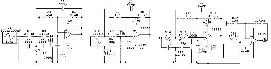
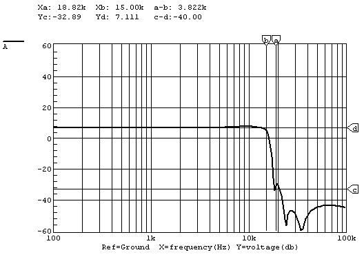
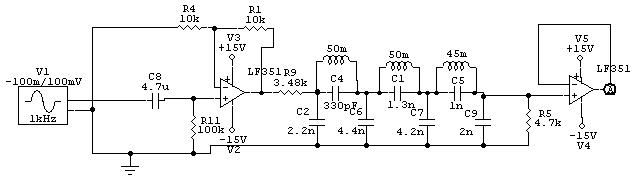
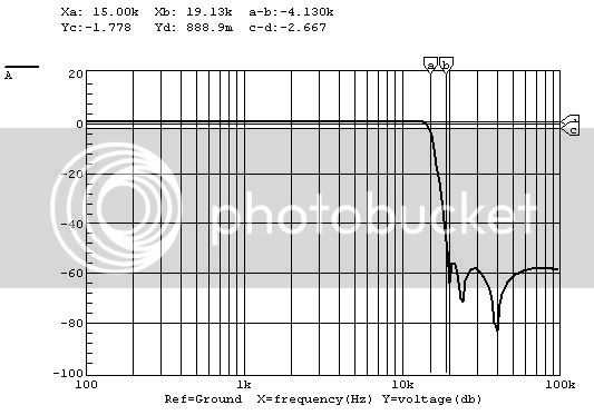
I'm looking for the schematic of a 16KHz low pass filter with the highest possible slope steepness. It will be used in the audio path of wireless in-ear systems to avoid any high audio frequencies (created by boosting using shelves) to upset the 19KHz pilot tone of the transmitter.


All reasonably simple schematics or ideas are very welcome!


Greetz,


Rogy
 
Be careful accounting for delays here. There is no limit to the steepness if you use digital domain processing but Nature will not be fooled.

You really need to specify at what level the disruption of your pilot tone system occurs to make an intelligent tradeoff. You want to use the minimum arrangement of poles and zeros to get adequate attentuation in the stopband, so that your delay is manageable in any real-time system like I assume this one is.

J_B_L once spent a couple of years and a few million to make a crossover system with ultra-steep slopes---more is better, right?

The thing turned out to be unusable for most of the intended apps in live concert work---the delay was about a tenth of a second!
 
Agree with Jakob, if all you really need is to attentuate at 19kHz. Even with the notch you will want no higher Q than necessary since again it translates into ringing and time domain artifacts. The simple twin-T is very broad however and may produce unacceptable attentuation below the notch. A bootstrapped twin-T can be adjusted to bring in the wings of the response as desired.

See for example

Variable Q twin-T
 
The presence of a 19kHz pilot tone tells me that there's L-R information (presumably on a 38kHz subcarrier) which needs to be protected, so a notch probably won't do the job. This is sounding an awful lot like commercial FM stereo, which presents the same lowpass-filtering challenge that Rogy describes, due to the 75uS pre-emphasis (50uS in Europe).

The designers of stereo FM exciters first tackled this problem decades ago, so it might be worth studying the design of a known good unit rather than trying to reinvent the wheel.

Here's a super-basic introduction to FM multiplex for those who aren't familiar:

http://www.smoke.com.au/~ic/mpx.html
 
If Dave is correct about your needs, there are some pretty good GIC-based lowpass filters shown somewhere in an Analog Dev. app note or op amp datasheet, for antialiasing signals before an ADC. You would simply have to scale the resistors up by the ratio of the frequency shown to your desired onset of rolloff.

In fact I found it:

AD713

See figure 43. You might want to tweak one of the zeros in the response to 19kHz.
 
Hi Jakob, Bcarso and Dave,


Dave's guess is correct; we're talking about commercial FM stereo. This technique is used in all professional wireless audio in-ear systems, but for some reason the built-in LPF very often doesn't do it's job good enough.

When audio gets in the way of the pilot tone, the receiver might lose track of it and switches to mono; this sometimes happens rhytmically (eg when a hi-hat contains audio information around 19 KHz) resulting in a stereo mix being made mono every time the hi-hat is played.

Very funny effect, but the artist goes crazy...


I discussed the problem with the designer of the world leading manufacturer of in-ear systems, and the guy told me to change my mixing habits ("don't use shelving hi boosts!"). I can do that, but I can't guarantee guest mixers who rent these systems from us do.

I asked him why they didn't improve the built-in LPF, but he claimed that would be very expensive. My guess is that it's not expensive when it's done correctly from the first time, but costs a lot of money if they have to modify the thousands of machines they already sold.

So I'll try to put a LPF in myself.


Thanks for the ideas!

To be continued...


Rogy
 
Rogy, it sounds as if the improvement wouldn't have to be too radical if the high hat effect is one of the few things to excite the dropout mode.

What are the size and power consumption constraints?
 
I'm guessing that it'll be at the transmitter end, and can be mains powered... unless you want to get very adventurous and tap it into the box itself, Rogy?

Maybe even stand alone as an optional "Plug through this if you have problems" box?

Keith
 
Hi all,


I would like to breadboard one stereo filter and test it; if it works well than I'd like to put six stereos into a 1" enclosure, which is to be placed in series with the desk's outputs (or can even be inserted over the aux masters...), so in front of the transmitters.

Power consumption is no issue. The filter will be mains powered.


Thanks!


Greetz,


Rogy
 
Ramsey Electronics (a supplier to the hobby trade) makes a kit that might fill the bill, or at least provide a platform on which to develop the idea. It costs 65 bucks:

http://www.ramseyelectronics.com/downloads/manuals/STC1.pdf

The online version of the manual does not include the schematic, unfortunately.
 
Well, the filter part is desccribed as an 8th-order 'butterscotch' at 15kHz, so that should be easy enough to draw out from textbooks.

Butterscotch filters are decent enough, couple that with a 19kHz notch and you should be completely bullet-proof.

If you don't like "Buttachunk" filters, try "Bissell", but for goodness' sake, make sure it's 'analag'!

:wink:

Keef
 
Yeah, the corner frequency is described as 15kHz on the first page, but later in the document they say it's 16kHz.

The Butterscotch has a gentle slope but at least it's less ripply-ringy than some. :wink:
 
[quote author="SSLtech"]

If you don't like "Buttachunk" filters, try "Bissell", but for goodness' sake, make sure it's 'analag'!

:wink:

Keef[/quote]

I'm looking forward to sweep-testing the Bissell:

http://www.bissell.com/main2.asp?Page_id=88&cookie_test=1

Brad
 
Hi all,

I'm back on this topic again.

I found an example of a 8-order elliptic filter in this document:

http://users.pandora.be/Rogy/Elliptical%20HPFs.pdf ; schematic at page 18 of the PDF.

The -3dB corner freq is 10KHz and it attenuates -80dB at 15KHz and above.

I simulated this circuit. I want to change the -3dB point to 15KHz and need to achieve as much attenuation as possible at 19KHz.

I tried to divide all component values by a factor 1.2666 to move the 15KHz point to 19KHz (19/15 = 1.2666) but that results in a -80dB point of 25KHz, so there must be a different scaling trick to be applied.

Anyone who can point me in the right direction?

The 19KHz point does not need to be -80dB down; it's more important that the frequency response remains flat upto 15KHz. So a lower order version of this filter might also do the trick.

Thanks in advance!


Rogy
 
Just checking & sorry for stating the obvious: did you also scale R ? Resistors in filters should stay unchanged when freq-scaling; just scale the caps.
 
Hooo boy. This is indeed an ambitious filter. I hope you can reduce the criteria described in the filter app note or you may find yourself with a need to trim each unit :shock:

Clintrubber gives correct advice for the simplest changes to get your result. But the big tolerance issue for this beast will be the capacitors, so if it were me I would design around a few specific values with high precision and adjust the resistors to fit. That is, you either change the caps or the resistors, not both---for higher freq one or the other get smaller.

When KEF used to design Friend filters for all their needs they used the same value cap everywhere possible and got a good deal on 1% tolerance 1nF parts. 1% caps are hard to come by in general and you will pay dearly.

Methinks there is another more elegant way to skin this cat. I would say I had a truly marvelous means to do it and the margin of my copy of Langford-Smith is too small to contain it :green: ---but I don't.
 
Me (being in passivePultecfilteringmode) would almost suggest to buy a few of these boxes

AUX-0025_lg.jpg


wideband_responsecurves.gif


http://www.audioprecision.com/index.php?page=products&id=1000001038

& mod & tweak !

But I'm not serious :wink:
 
bcarso wrote on page 1
Rogy, it sounds as if the improvement wouldn't have to be too radical if the high hat effect is one of the few things to excite the dropout mode.

Makes sense to me. Building the brickwall filter they "should have" used in building the transmitters sounds like going at it the hard way, especially if you haven't tried adding a notch around 17-21 khz yet to see if it won't do the trick. Adding a simple notch filter to what you've already got included in the built-in transmitter flters like bcarso suggested is easy and cheap. With a fairly sharp notch you can probably pull the existing LPF slope down fast enough to keep the high-hat from throwing the receivers out of lock. Like a Chelby LPF. It's for monitoring, and since it's just adding an anti-resonant tuned circuit, it won't ring like a true Chelby LPF.

And FWIW, I'd suggest you consider adding a simple L-C tuned circuit - yeah, it's old tech, but it has high Q and is simple to adjust. And I bet you can pick up the components cheap as surplus parts, too. Old FM tuners used them by the millions.

And if it works, making and tuning twelve of 'em is easy. Using gyrators and such are important when alignment is costly (i.e., mass production), but for 12 filters, it's probably less trouble than the brickwall approach. IMHO.
 
Hi,
In the pictures below there are two LPF 15kHz filters (active and passive) that I tend to use quite often.
All caps are styroflex, mica or mk* 2%, all resistors are 1% metalfilm, inductors are trimmable.

Active filter, circuit:

mpx_lp_active_circuit.jpg


Active filter, simulation result:

mpx_lp_active_wave.jpg


Passive filter, circuit:

mpx_lp_passive_circuit.jpg


Passive filter, simulation result:

mpx_lp_passive_wave.jpg


I hope you find this helpful.

Regards,
Milan
 
Back
Top