Biasing CA3080's - or NTE 996

GroupDIY Audio Forum

Help Support GroupDIY Audio Forum:

This site may earn a commission from merchant affiliate links, including eBay, Amazon, and others.

Milkmansound

Well-known member
Joined
Jan 29, 2005
Messages
449
Location
San Francisco, CA
How do I go about biasing these? There is no application diagram on the NTE datasheet.

Right now I am using a 3.9k resistor tied to ground via a .01n cap - something I grabbed from a theremin schematic - am I headed in the right direction?
 
ok, nevermind - I found the original datasheeet - looks like I was a tad off:

application3080.gif
 
What are you using them for? The app diagram is for an op amp application, about the most unneeded circuit one could imagine. That is, one wouldn't use an OTA for an op amp except if it were sitting there doing nothing (say the unused half of a dual OTA).

The typical use of an OTA is something that takes advantage of its variable transconductance, so the biasing is part and parcel of the circuit details.
 
ok - I am using it for this MS20 filter clone project - schematic is here:

http://www.uni-bonn.de/~uzs159/rs20.png

there is no mention of the biasing on the schematics - I assume that there is biasing of some sort in the circuit.

Thanks for checking this out. :grin:
 
Looks like the only thing not shown on the filter circuit is the power supply rail connections. It would be nice if the schematic showed the pin numbers though.

Looks like the transconductance control pin is pin 5 (shown on the schematic as the leads going in vertically to the middle of the 'infinity-sign" at the outputs of O1 and O2). The inverting and noninverting input pins are 2 and 3 respectively, and +V is pin 7, -V is pin 4. The current output is pin 6 (horizontal line into the infinity sign).

That's all the biasing required. For the dual OTAs (LM13600 or LM13700 or NE5517) there are input predistortion diode-connected transistors available which do share a common "anode" connection that is brought out to a pin. This can be left floating or used in various ways.
 
(stifles a curse for schematics without reference designators)

No---they tie to the two 10k resistors above, whose other ends tie together and to the right-hand PNP transistor.

The 10k R's divide the control current out of the PNP in equal parts to control the transconductance of each OTA, which in turn determines the filter frequency.
 
> leave pin 5 floating?

No.

The 3080 is an op-amp PLUS a throttle control. You NEED current into pin 5; otherwise the 3080 is throttled OFF.

Around 1mA of current gives Full Gain.

At zero current you get zero gain.

Zero gain is not very interesting.

In this case, the overall gain is the throttle-controlled gain limited by the cap loading the 3080 output and the overall 10K,10K feedback loop. Low frequency gain is always 10K:10K= 1:1. Highest frequency gain is always zero because of the cap. So the response is flat up to some medium frequency, and then falls off. The point where it changes from flat to fall-off is set by the cap (fixed) and the current into pin 5 (variable by A4 and all the stuff top-left).

With two such low-pass filters, closely tracking, and feedback through the Resonance side-chain, the low-pass can be a peaking filter.

The whole point is that you can get a one-knob tunable filter with multiple current-controlled 3080s. If you wanted a fixed-frequency filter, you could do that a lot simpler than a bunch of 3080s and their control system.

The circuit is correct and workable as drawn. It does not need re-engineering. If you only want a manual-knob filter, you will never use it with analog synth or other voltage-control systems, you can omit some of the top-left stuff, but I would leave it all in.
 
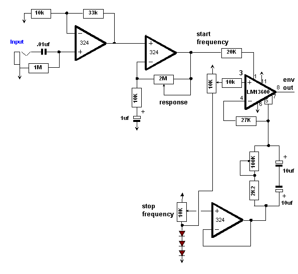
Just in case this was missed, it's actually a very clever circuit providing rising or falling envelopes depending on the settings of the start and stop frequency pots, and more importantly, if used with guitar, provides an almost jitter free sweep for a VCF.
Stephen
 
[quote author="StephenGiles"]Just in case this was missed, it's actually a very clever circuit providing rising or falling envelopes depending on the settings of the start and stop frequency pots, and more importantly, if used with guitar, provides an almost jitter free sweep for a VCF.
Stephen[/quote]

It's a very nonlinear beast to say the least. I have a truly marvelous analysis, but the margins of my databook are unfortunately too narrow to contain it.
 
That's a very nice looking circuit in my view. I might even try it with my sweep generator, which although designed with guitar effects in mind, could be matched to the MS20 filter. If you or anyone else would like to see the original using a CA3094 (the guvnor of OTAs!) I will post it. Liitle has been said here about that chip, now discontinued, but can still be found.
Stephen
 
It's here, a little feint now after 25 years!
http://img.photobucket.com/albums/v317/StephenGiles/EHspacedrum.jpg

The chips marked 1048 are CA 3094. I have an almost complete redraw of this circuit somewhere, and a circuit description. Note the use of LM324.
Stephen
 
[quote author="Milkmansound"]ok, so the infinity sign is just the junction between the 2 pins, and the "throttle" is going to be floored!

thanks[/quote]

I don't understand you. Have you looked at the datasheet for the CA3080? The circuit symbol in the schematic is standard but the absence of pin numbers may make it difficult to understand.

Perhaps a better schematic would just show a block with pin numbers. If it did the traces from the two 10k R's from the PNP collector would terminate in pin 5 of each 3080. Period, end of story. The current outputs of the 3080's are on pin 6 of each and would tie to the 1nF caps and op amp inputs. Period, end of that story.

The transistor sources a current, divided equally by the 10k resistors, so half flows into each Iabc input of each 3080. That is the "throttle" control, and it is not "floored" but is set by the control voltage ("pitch") and potentiometers. There is no direct connection between the Iabc's and the outputs of the 3080's---they are separate pins.
 
oooooh - I got you. Please excuse my ignorance - but I do have an excuse, because mouser subbed me NTE IC's and the datasheet is not that thorough - or its me just being kind of a newbie.

so the 10k resistors control the bias and are not tied into the outputs at all - the infinity sign threw me off because I had never seen that before. Should be good to go! :idea:
 
[quote author="Milkmansound"]oooooh - I got you. Please excuse my ignorance - but I do have an excuse, because mouser subbed me NTE IC's and the datasheet is not that thorough - or its me just being kind of a newbie.

so the 10k resistors control the bias and are not tied into the outputs at all - the infinity sign threw me off because I had never seen that before. Should be good to go! :idea:[/quote]

:green: :thumb:
 

Latest posts

Back
Top