1+1 : 1+1 transformer wiring

GroupDIY Audio Forum

Help Support GroupDIY Audio Forum:

This site may earn a commission from merchant affiliate links, including eBay, Amazon, and others.

saint gillis

Well-known member
Joined
Nov 4, 2012
Messages
920
Location
Brussels - Belgium
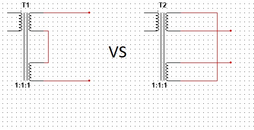
Suppose I have a 1+1 : 1+1 line input transformer, for instance a LL1540, loaded at the secondary by an op amp.
  - If I want to use it as 1:1 I should wire both the primary and secondary in series right?
  - If I want to use it as 2:1 I should wire the primary in series and the secondary in parallel?
  - What about if I want to use it as 1:2, should I use only one primary winding or should I wire the primary in parallel?

Now suppose it is a 1+1 : 1+1 line output transformer, driven by an op amp,  say a LL1517...
  - Used as 1:1, the windings should be wired in series
  - What about 1:2 and 2:1 configurations? one winding in series and the other in parallel?  or is it better to leave one winding floating?
 
parallel is the way to go,

especially if it is a dual coil design with UI lams, C core, 

it does not change he primary inductance, it just splits the current between two conductors wired in parallel, the turns count stays the same, 

 
CJ said:
parallel is the way to go,
it does not change he primary inductance, it just splits the current between two conductors wired in parallel

Thank you, I'd have thought it would have affected the input impedance of a line input transformer for instance.
 
RuudNL said:
IMHO connecting windings in parallel (as opposed to using a single winding) only changes the impedance, not the transformer ratio.
It does not change the nominal impedance, however it improves coupling between primary and secondary, which reduces the leakage inductance and improves HF response.
OTOH connecting windings in series quadruples the inductance, thus the nominal impedance, and increases the leakage inductance and DC resistance, both of which impair HF response.
But remember that nominal impedance is just a ballpark figure, made for estimating suitability.
 
Abbey said "connecting windings in series quadruples the inductance" so for an input transformer it reduces HF response, if you use a very good transformer with HF roll-off far beyond audio-band it will cut more high frequencies but if you use a transformer with a HF roll-off closer to the audio-band you could affect your frequency response by getting a HPF or a resonance peak between 15KHz and 20Khz ...
 
noise will go up a bit with series the series connection, but this is a twin coil job so E fields from outside will cancel, 

leakage will go up but Lundahl stuff usually has very good HF specs, so you might drop from 100 K Hz to 50 K Hz, who cares but the dog?

the 1540 cut sheet says use series connections for hi z operation, this looks to be a 10K to 10K bridging,

do not think it will do 20 dB at 5 Hz on a core that size so be wary of your input levels at low F.
Lundahl knows this so he put the distortion specs at 50 Hz where the transformer will tolerate 10 times the level,

 
ran across an old dissection of a McMudy  2001     
1:2 input transformer where we compared primary hookups,

here is the graph of the unloaded secondary with one primary, series and parallel primaries,

normal output was 5 and 10 volts (series and parallel, changes the turns ratio)

series and parallel looked about the same the voltage difference at resonance is due to the turns ratio being twice as high for parallel connection

this is a 600:2.4K, so your 1540 will react differently as it has many more turns,
 

Attachments

  • primay series parallel.JPG
    primay series parallel.JPG
    183.6 KB
CJ said:
ran across an old dissection of a McMudy  2001     
1:2 input transformer where we compared primary hookups,
That's very interesting info. One thing that is not immediately obvious is how damping affects response. These measurements have evidently been done with the same signal source; the series connection shows that the HF peak's amplitude is  lower.
 
yes

three things you need to ponder

1) connect the secondary windings in series without having them cancel each other,

2)  keep the whole mess in phase with the primary.

3) top secret hookup for less noise -  tricky hookup by whereby the outside ends of the secondary are tied to ground and therefore shield the inner windings,  might not make any difference with a low z/ low tuns wind,

this is how a lot of power transformers are wired, only the reason they do that is to keep flux from radiating outward, so if the center splice is earthed, you have two shields,  for audio, it might help keep capacitance down or balance the capacitance, or both.

if not earthing the CT, then just do the normal hookup,

use the dots on the data sheet they are your friends for easy hookup,

all dots on top or all dots on bottom to be in phase
 

Attachments

  • series.png
    series.png
    12 KB
CJ said:
yes

three things you need to ponder

1) connect the secondary windings in series without having them cancel each other,

2)  keep the whole mess in phase with the primary.

3) top secret hookup for less noise -  tricky hookup by whereby the outside ends of the secondary are tied to ground and therefore shield the inner windings,  might not make any difference with a low z/ low tuns wind,

this is how a lot of power transformers are wired, only the reason they do that is to keep flux from radiating outward, so if the center splice is earthed, you have two shields,  for audio, it might help keep capacitance down or balance the capacitance, or both.

if not earthing the CT, then just do the normal hookup,

use the dots on the data sheet they are your friends for easy hookup,

all dots on top or all dots on bottom to be in phase

Is there a particular reason why you connected the lower terminal of the lower secondary to the upper terminal of the upper secondary, rather than connecting the lower terminal of the upper secondary to the upper terminal of the lower secondary? I've seen what you done also being specified by Lundahl, but to me there is no difference, a coil is a coil is a coil, so to me it shouldnt matter if you put the bottom coil in series with the first coil or the other way around. Im including an image of what im talking about,

trafos.jpg
 
Dualflip said:
Is there a particular reason why you connected the lower terminal of the lower secondary to the upper terminal of the upper secondary, rather than connecting the lower terminal of the upper secondary to the upper terminal of the lower secondary? I've seen what you done also being specified by Lundahl, but to me there is no difference, a coil is a coil is a coil, so to me it shouldnt matter if you put the bottom coil in series with the first coil or the other way around. Im including an image of what im talking about,
You're right; there shouldn't be any difference, except for the fact that stray capacitances may interfere. There are some cases where there is a noticeable difference in HF response; in one configuration, capacitive coupling may acts as an HF boost and in an opposite configuration act as an HF cut.
Specific analysis of the xfmr construction and the drive circuit is required to perfect undesrtand and quantify these effects.
The LL xfmr's construction is supposed to be perfectly symmetrical, so I don't expect any of these effects.
 
Back
Top