BradM
Well-known member
Hi all,
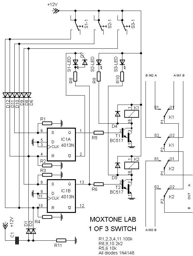
I'm trying to create an input selector switch for 3 input sources. I'd like to have three momentary pushbutton switches control some logic circuitry that allows me to actuate relays that switch between A, B, and C. For instance, when the unit is powered on it defaults to input A. Then if I press C it turns off A and B and turns on C. If I then press B it should turn off A and C and turn turn on B. If I were to press B again, it should do nothing. And so on.
If it was simply two inputs I could easily implement a flip flop circuit using a NAND gate that would do the trick nicely. I thought I could use a 3-input NAND gate to do what I wanted, but when built the circuit, I could only get it to switch between any two inputs, while the third input source would always stay high.
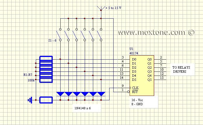
Does anyone have any insight how to make this kind of thing work using 4000 series or similar logic gates?
thanks,
Brad
I'm trying to create an input selector switch for 3 input sources. I'd like to have three momentary pushbutton switches control some logic circuitry that allows me to actuate relays that switch between A, B, and C. For instance, when the unit is powered on it defaults to input A. Then if I press C it turns off A and B and turns on C. If I then press B it should turn off A and C and turn turn on B. If I were to press B again, it should do nothing. And so on.
If it was simply two inputs I could easily implement a flip flop circuit using a NAND gate that would do the trick nicely. I thought I could use a 3-input NAND gate to do what I wanted, but when built the circuit, I could only get it to switch between any two inputs, while the third input source would always stay high.
Does anyone have any insight how to make this kind of thing work using 4000 series or similar logic gates?
thanks,
Brad


![Soldering Iron Kit, 120W LED Digital Advanced Solder Iron Soldering Gun kit, 110V Welding Tools, Smart Temperature Control [356℉-932℉], Extra 5pcs Tips, Auto Sleep, Temp Calibration, Orange](https://m.media-amazon.com/images/I/51sFKu9SdeL._SL500_.jpg)


")