3-way input selector using CMOS gates

GroupDIY Audio Forum

Help Support GroupDIY Audio Forum:

This site may earn a commission from merchant affiliate links, including eBay, Amazon, and others.
There are always multiple ways to skin any cat, even when limited to only 4000 series CMOS.

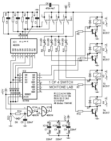
If you simplify this to it's essence, you want to latch a switch state. The all too popular flip flop comes to mind, but that only provides two output states. What you need is a parallel D type (data type) shift register or latch with 3 or more bits. The manual switch both sets up the new conditional data and clocks the new data into the latch or register.

Things to consider are set up time for the input data to be valid, typically with respect to a clock edge. The 40174 latches on the positive going clock edge. From looking at the data sheet clock timing diagrams, they reference everything to 50% of clock voltage, while the data input appears to be processed through a Schmidt trigger, i.e. valid low needs to be <30% and valid high needs to be >70%. This is useful for noise immunity but for this application looks like the clock would switch before the data is valid. The diode drop in series with the clock helps in the right direction but may not be enough?? Since the circuit as drawn is tested and works apparently, perhaps there is some switch bounce and later clock pulses actually latch in the data after it has time to set up.

From the data sheet it appears we could benefit from a slightly delayed clock. A small RC in series with the clock might add a little delay to insure the data has set up reliably before the clock pulse comes along to latch it. In general slow clock edges are problematic because noise can cause multiple clock hits, but in this case multiple clock hits will just latch the same data so will look stable at the output. 

Using DPDT relays to provide some extra logic is clever, but limits the solution to only 3 states and is hard to expand to more inputs.  In general for such things it's good advice to KISS (keep it simple).

I was a big fan of 4000 series logic a few decades ago, but these days I'd be inclined to use a micro... while something this simple is overkill for even the simplest micro.. Of course once you add a micro, you will find other things to do with it.

It's useful to understand latches and shift registers because they are often the glue used with micro's to interface with the outside world. 

JR
 
Hi Brad,

Thanks for the email. I have already replied.

As regards the 1st circuit, I'm figuring out where things might have gone wrong for you and as soon as I come up with something, I'll let you know via email. In the meantime, you may wish to try circuit 2, which is both simpler and more elegant.

Regards,
Milan
 
JohnRoberts said:
Using DPDT relays to provide some extra logic is clever, but limits the solution to only 3 states and is hard to expand to more inputs.  In general for such things it's good advice to KISS (keep it simple).

I was a big fan of 4000 series logic a few decades ago, but these days I'd be inclined to use a micro... while something this simple is overkill for even the simplest micro.. Of course once you add a micro, you will find other things to do with it.

JR, I totally agree.

But, as I understand it, Brad's circumstances are such that micro's are really out of question here. Within his technological limitations, I think circuit no. 2 is the best that can be done in designing a simple CMOS 3-input switching circuit.

Regards,
Milan

 
Have I missed something really obvious here?
3 sticks of logic, plus supporting passives etc can be replaced by a single micro.

I know Brad has said that he wants to do it in the analog of 4000 domain... what I'm struggling to understand is *why*.

simply saying that he doesn't have the programming experience shouldn't limit this effort.
http://focus.ti.com/docs/toolsw/folders/print/ez430-f2013.html is a $20 dev kit, that includes the IC on a pcb that he can bluewire out.

I already have code that does what he wants...

/R

 
Rochey said:
I know Brad has said that he wants to do it in the analog of 4000 domain... what I'm struggling to understand is *why*.

Your youtube video must have scared him off. ;D

Regards,
Milan

P.S. Just joking, loved the vid.
 
moamps said:
JohnRoberts said:
Using DPDT relays to provide some extra logic is clever, but limits the solution to only 3 states and is hard to expand to more inputs.  In general for such things it's good advice to KISS (keep it simple).

I was a big fan of 4000 series logic a few decades ago, but these days I'd be inclined to use a micro... while something this simple is overkill for even the simplest micro.. Of course once you add a micro, you will find other things to do with it.

JR, I totally agree.

But, as I understand it, Brad's circumstances are such that micro's are really out of question here. Within his technological limitations, I think circuit no. 2 is the best that can be done in designing a simple CMOS 3-input switching circuit.

Regards,
Milan

Yes.. I am talking about "my" inclination not suggesting what he should do. For a one off simple project it doesn't make sense to learn a new technology (programming micros).

Using a a D type SR latch is the most straightforward approach..  I have done more than my share of trick circuits with 4013s also capable of d-type latching.

Within the constraint of 4000 series logic, I prefer the first circuit, but with some consideration for the clock latching at 50% and data not being valid until 70% of PS rail voltage.

JR

 
Hey guys,

Maybe I shouldn't rule out using a microcontroller.  Admittedly I know absolutely nothing about them.  But if it's simple to use and implement then I'm willing to consider it as a viable option.  I was telling Milan over email that I just learned how a flip flop worked two days ago.  And I'm still trying to grasp the basic concept.  ;D  I'm venturing into uncharted territory here.  Haha.  I have so much to learn to come upto speed on this stuff!

When I initially posed my question it was from a very ignorant perspective about all the potential options.  I was merely looking for some general direction to help advance my understanding of the general concepts.  John's post at the top of this page was excellent by the way.  And PRR's book recommendations--thanks for that!  I totally wasn't expecting Milan to jump in and offer up a working design, but I'm glad he did because it's been very helpful for me to study and build and test.  I'm very much a hands-on kind of learner in that sense.  

Before anyone spends any more time doing my design homework for me, I do feel compelled to let folks know that I'm working on a commercial product that will utilize switchable inputs.  CMOS switching is one option I'm entertaining to accomplish my goal.  This is only a very small part of the overall function of the unit.  I already have some other schemes worked out, but would love to expand my understanding of gates, flip flops, etc., hence why I posted my general question in the first place.  I would never want to capitalize on anyone's intellectual property without express permission.  So when Milan posted his schematics I contacted him immediately to disclose all this to him and offer to compensate him for any design he helped me work out.  Milan has been generous enough to offer to share his knowledge with me.  In the true spirit of this forum I'd like to share any final designs for logic switching I develop with the community in return (assuming that's okay with Milan).  

If I'm stepping out of bounds in any way please let me know because I definitely want to be mindful of the rules, while at the same time helping to contribute to the wonderful collection of knowledge that abounds here.

Thanks all,
Brad
 
Yes, this is important to know...

Microprocessors are a different discipline, and if you go that way, you will have the capability to do a lot more. Like remembering what state you were in when power was turned off, adding turn on delay muting, lots of stuff, just about whatever you can imagine.

Cost analysis all depends... You can eliminate all or most of the glue parts (diodes, resistors, etc). These days where it cost more to place a simple passive part than buy it, eliminating multiple parts could make a difference.

Figure out what you are trying to accomplish.. just making a one off, suggests an old school approach... future technology with more options for feature expansion, suggests micros.

JR
 
Thanks for the insight, John.  It would definitely be cool to remember which state I was in when before I turned off, although not entirely necessary I guess.  It's fairly easy to just have the unit default to input A at each power up.

Here's a dumb question--I'm assuming you have to program microcontrollers via some external means.  How is that typically done?

thanks,
Brad
 
Most micro vendors supply free or inexpensive PC based programming/debugging environment software. Usually there is a modest cost programming dongle that connects between a USB port on the PC and the chip you want to program. You can also buy modest priced demo PCBs with a micro and related glue parts so you can hit the ground running. Using a typical debugging environment you can single step through your program and see almost clock tick to clock tick behavior.

I will resist the temptation to argue for using the same micro family I do, but there are several similar micro families with sufficient onboard flash memory to hold much larger programs than you or I would ever write.

Modern micros also have multiple modest resolution A/D and PWM or D/A convertors buit into them, so you can do lots of tricks with what are one chip or only a handful of ICs solutions.

I am an old analog designer, but I have been seduced by the ability to use nonlinear decision making inside a micro environment, to make smart decisions about how to respond to simple inputs based on multiple data and even recent history.

JR
 
If there is a micro family you could point me towards to begin my education, I'm all ears. :)  You have piqued my curiosity!  I know I could write a BASIC program to do what I want to do rather easily.  I'll need to brush up on my programming skills of course.  :D

Brad
 
you might want to do some googling on the arduino platform... seems popular for people just starting off.

my preference, and tool of choice - msp430. but then, I work for TI (the manufacturers of the '430) so my opinion is biased. I think they are awsome... i couldn't write a line of code on them 2 years ago.
 
There is a tendency for engineers to become attached to the first family they learn to design on, so I am familiar with and comfortable designing with microchips PIC family, http://www.microchip.com/stellent/idcplg?IdcService=SS_GET_PAGE&nodeId=2629&param=en533465    but I have no illusions that they are significantly better or worse than others. Kind of like Fords and Chevys, the car lovers will tell you one brand is great and the other brand sucks, when they are roughly equivalent.

The 8051 family of micros is well established and has been around for a long time. I actually like the feature mix of the 8051 better than the PIC family I use, but not enough to change platforms.

I prefer to write code in machine language, but there are C compilers for most families.

If i were you I would suggest doing some homework and maybe even setting up a spreadsheet with features and whatever is important to you, now and in the future. I started writing on a 8 bit PIC but jumped to a 16 bit family and while different, it was actually easier than trying to deal with the world using only 256 shades of gray...

I suspect you can get others to chime in with their personal favorite platform. Good luck and don't marry the first girl who gives you a piece of ___. 

JR
 
Brad McGowan said:
If there is a micro family you could point me towards to begin my education, I'm all ears. :)  You have piqued my curiosity!  I know I could write a BASIC program to do what I want to do rather easily.  I'll need to brush up on my programming skills of course.  :D

Brad

Well, you are already there. Get a PicBasic compiler. Just google and you'll get tons of it (MeLab in US offers one). You will be up and running in a matter of days. End of story. As John and the other guys said, it is a whole different world with incredible possibilities that would otherwise break even the most experienced digital designer's back using 4000 series stuff.
 
Rochey said:
simply saying that he doesn't have the programming experience shouldn't limit this effort.
http://focus.ti.com/docs/toolsw/folders/print/ez430-f2013.html is a $20 dev kit, that includes the IC on a pcb that he can bluewire out.

Any chance of a coupon code for forum members to help defer the shipping charge?
You are pitching it. . .
Mike
 
> i couldn't write a line of code on them 2 years ago.

Are you saying it took only two years to write one line of MSP430 code? <G>

> I know I could write a BASIC program

The level of abstraction needed for this project is "hardly" higher than raw machine code. Far less than a classic COBOL or BASIC. But I do think you want the ability to assign mnemonics to real-world actions. "FLAME ON" is clear, bit-boffing a mystery address in RAM is not. Yes, many of the compilers let you define FORTRAN-like names to registers and even pins.

> I prefer to write code in machine language

Large jobs in small chips with a smart/experienced programmer, absolutely. Your drum tuner has a lot to do, and (hoped-for) production quantity justifies a week of tedious coding to use a buck-cheaper chip.

> a micro family you could point me

For a one-off, IMHO: BASIC Stamp. It is pre-packaged so a kid can build stuff in an hour. I'm no kid and I had a fan-timer prototyped in a few easy days. I just tacked a couple LEDs on, "pushbuttoned" with a bare wire.

You write code on the PC. IIRC the interface will error-check, and may even simulate a RUN on the actual Stamp, with register-peek. Just about like MS QBasic, except you plug your Stamp and press "Load" so your code is copied into the Stamp.

When my code ran and ran the LED 10 seconds after a push, I changed a constant to make it run minutes and added the TIP120 and a relay. The biggest glitch was that my 12V relay worked when a 9V battery was fresh, not when it got weak.... the final hardware would have honest power so that was moot.

> remember which state I was in

That requires standby power or a non-volatile memory. AFAIK the Stamp does not do that, there are add-ons with Flash storage (or for ~~30uA the Stamp will sleep yet retain state). Some other chips do have non-volatile storage.

> working on a commercial product

Ah, for more than one, BASIC Stamp protoboard cost and size may not be suitable. They do sell the naked chip: proto on the Stamp-board, copy the key connections to your PCB, dump the same code.

But there are other chips at lower prices. PicBasic compiler will take BASIC-like instructions and run on $2 PIC chips.

> The 8051 family of micros is well established and has been around for a long time.

I remember when that thing was new. It seemed a little lame. I'm astonished that it just won't go away, has even gone to Mars (as 80C51).

Intel HEX may not be Brad's solution, but for many projects it is.
 
PRR said:
> I prefer to write code in machine language

Large jobs in small chips with a smart/experienced programmer, absolutely. Your drum tuner has a lot to do, and (hoped-for) production quantity justifies a week of tedious coding to use a buck-cheaper chip.

I am a self taught programmer (ignoring one fortran class in 1966, and one night school C class in the '90s). I bought the C compiler for my original 8 bit PIC platform, but found the fine timing and literal control of pins and ports easier to manage at machine level. I also ran into timing overhead issues, where I only had a finite number of clock ticks within an interrupt to accomplish a task, before the next interrupt over ran it. I can't imagine any C compiler getting that job done easily. If I was a professional coder I would surely use high level languages as micro power is relatively cheap compared to programmer time, unless volume is really huge.

I have since moved to a more powerful and faster 16 bit family which very nicely is also cheaper (win win).  I don't think I could ever be induced to go back to an 8 bit environment even if the micro was free...let alone a little cheaper. 256 is a surprisingly inadequate number of flavors for dealing with the real world. 

Non-volatile memory is included in the $2-3 PIC parts I use, but this processor is clearly overkill for managing 3 buttons.  The stamp may be a good way to dip your toe into the water since you won't be tempted to stay with it for serious designs, but the OP did mention he was working on a commercial design.

He doesn't need a 16 bit part, or a micro, but that's what I would use, and add a bunch o'tricks.. to justify it.  ;D  C compilers are not free so cost of language tools may advise the poster toward his solution.

If memory is not a benefit, and he only needs the simple 1 of 3 input selector, CMOS is not a bad solution.  For what it's worth the CMOS  can be kept alive with less current than most micro's, so even that is an option if the unit remains plugged into the main power. The cmos could hold it's state down to 3 volts or so, and draw less than a leaky cap.

JR
 
I have modified Circuit 1 from the previous page to incorporate IC1, which does not allow more than 1 source to be selected. I also added a small delay circuit (IC3) to the clock line of IC2 to ensure reliable latching at all times. Even without the delay circuit, the whole thing worked fine but now, with this simple upgrade, different operating conditions and chip characteristics are eliminated from the equation altogether.

The circuit has been tested and is fully functional. It has 4 inputs but can easily be reduced to 3, if necessary.

I hope somebody will find this exercise useful. My work here's done.  :)

Regards,
Milan

1-4%20switch.JPG
 
Not to distract from the PIC and CMOS discussions.... but I did this kind of thing a while back with just momentary switches, diodes, and latching relays.

Essentially, the momentary switch sent 9v (or whatever you need for relay's plus your diode drop) to 3 diodes that reset the 3 relays except for the one you want to switch on - which is sent to the "set" contacts.  The next switch is similiar except it switches "set" to relay 2 and "reset" to the other 3 relays and so forth.

Sure... it's a pain to veroboard, has 16 diodes for a 1 of 4 switch, but it remembers your last selection (on power on) and doesn't involve any code.

CC
 
Back
Top