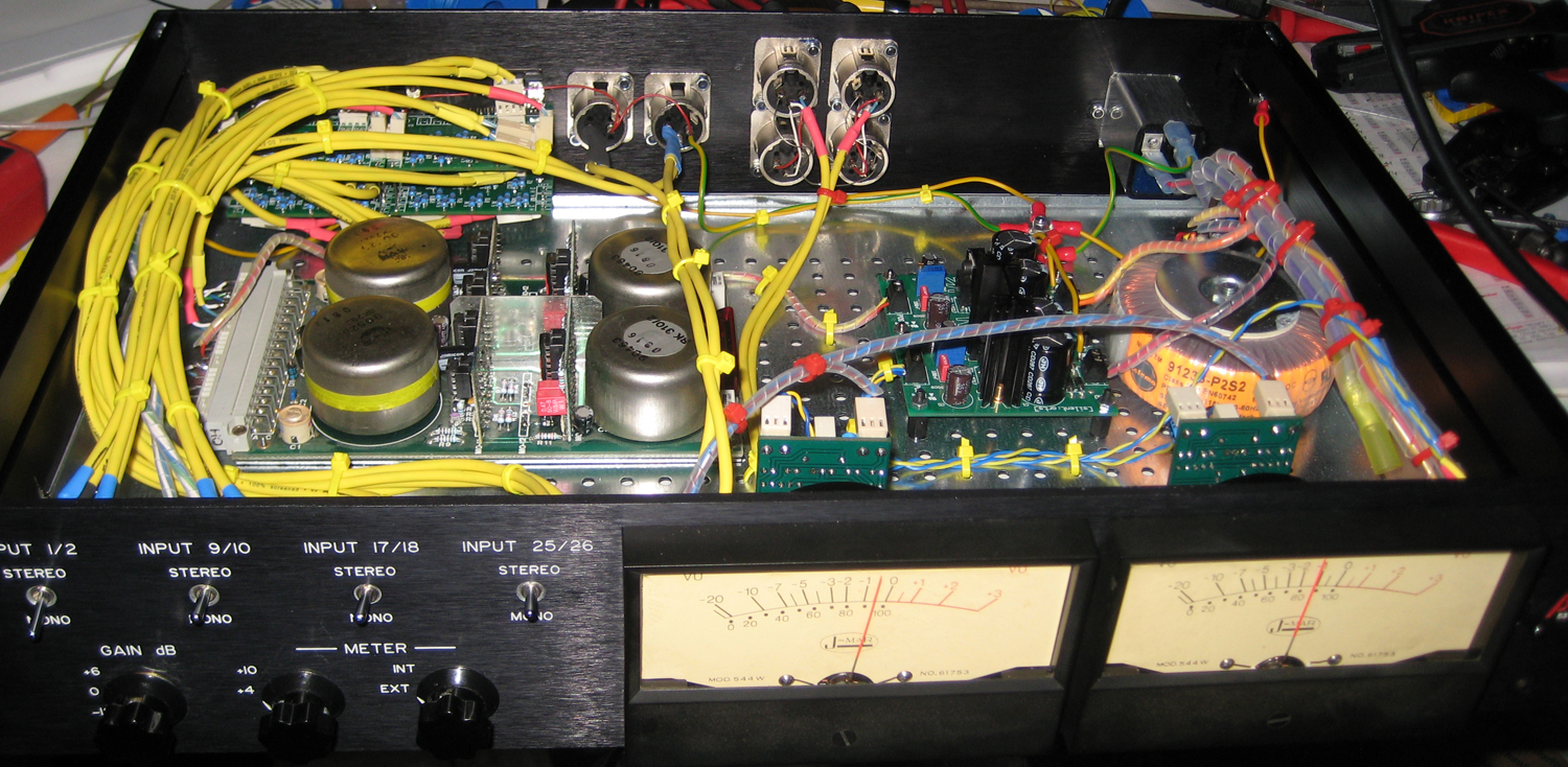
32:2 summing device with Neumann V475-2C (pics)

GroupDIY Audio Forum

Help Support GroupDIY Audio Forum:

This site may earn a commission from merchant affiliate links, including eBay, Amazon, and others.

Holger

Well-known member
GDIY Supporter
Joined
Jun 11, 2006
Messages
896
Location
Hamburg, Germany
I've recently finished a 32:2 summing device. Nothing so exciting but people like to see pictures of finished devices  ;)

- External meter input, old Bach-Simpson meter buffered with JLM meter buffer
- Modushop case with inner base
- Neumann V475-2C card, recapped
- two PSOPSUs, one for the audio part, one for the buffer

SuMiFront.jpg


SuMiRear.jpg


SuMiIn.jpg

 
Very nice build Holger - top shelf :)

Inspiring me to finish my neve style summing box!


Cheers
 
Very good quality build. I particularly like the base of the enclosure with all its ready made mounting holes. Where did you get that from?

Cheers

Ian
 
Wooow. That's the most beautiful build I have seen in month. Love the small wire wrapping. Thats PRO

Thanks for sharing.

Cheers
Soren
 
Very nicely done.  I'm looking into doing something similar.

Where did you get the enclosure made?

Thanks,

-JP
 
Hi!

I'm on a similar build at the moment (24:2 with a V475 card), and i try to figure out how to add a stereo <-> mono switch for the first 6 channels.

First of all, i want to know if i get this straight: the symmetrically interconnection sends two signals with inverse polarity to the cards transformer, and after that the signal gets unsymmetric (sorry, i don't know the english word for that  ::) ) within the op-amp. Because the signals are 100% correlated, there is a increase of +6dB (Voltage, i guess). Is that correct?

Secondly, if you want to add a mono Signal without using a stereo input, you have to 'clone' the signal for both channels. As far as i can tell, there will be another aditional increase of +6 dB because now there are 4 similar, 100% correlated signals.

My question would be: if my input resistant for the normal symmetrically signal is 5,1k, what should the input resistans for the mono signals be to get the same level? And do i need to put two resistors before the Y or after? as far s i can tell the second version would be the right one, because i don't shorting the symmetric bus. (see picture)

I really would appreciate your help!

Cheers, Tomess


Attachments

  • IMAG1758.jpg
    IMAG1758.jpg
    664.8 KB
I think you first need to define what you want your stereo/mono switch to do. Obviously in stereo mode, channel 1 is routed only to the left bus and channel 2 to the right bus. What do you want to happen in mono? Do you simply want channel 1 to be routed equally to the left and right buses so it is panned centre. Do you want the same to happen to channel 2 at the same time?

I suspect the answers to the above will be yes. If so then you need to decide how much to drop the level in each channel when they are panned centre. Opinions differ on the best value but somewhere in the 3dB to 4dB region is normal. To reduce the level fed to a bus by 4dB you simply increase the resistor values by 4dB or about 50%. So with  5K1 bus resistor you would need to add about 2K5 in series (2K4 would do fine). So both channels need to have 2K4 series resistors added and a switch added so they can be switch in for mono mode. As well as this, channel 1 also needs feeding to the right bus and channel 2 to the left bus via 5K1 + 2K4 resistors. These also need to be switched in when the mono switch is operated. Lastly, you need to make sure that in stereo mode, the additional 5K1 +2K4 resistors are connected to each other instead of to the inputs in order to ensure the bus impedance is not altered. As you can see the switch needs quite a lot of poles which is why I suspect Holger did it with relays.

Hope that helps.

Cheers

Ian
 
Hey Ian, thanks alot for your quick reply!

ruffrecords said:
Do you simply want channel 1 to be routed equally to the left and right buses so it is panned centre. Do you want the same to happen to channel 2 at the same time?

That's exactly my goal!Then it is possible for me to only use 2 outputs for mono kick and mono snare at the same time, for example.


ruffrecords said:
If so then you need to decide how much to drop the level in each channel when they are panned centre. Opinions differ on the best value but somewhere in the 3dB to 4dB region is normal.

Well, the summing amp will be in my signal path all the time so i might set the levels IDB and don't 'shrink' something to mono in the process. It just to have the possibility to decide how many mono signals (depending on the projekt) i can use and don't waste any precious outputs on my soundcard. If there are slight differences in levels, i don't mind. However, it's good to be as precise as possible.  ;D

ruffrecords said:
To reduce the level fed to a bus by 4dB you simply increase the resistor values by 4dB or about 50%. So with  5K1 bus resistor you would need to add about 2K5 in series (2K4 would do fine). So both channels need to have 2K4 series resistors added and a switch added so they can be switch in for mono mode. As well as this, channel 1 also needs feeding to the right bus and channel 2 to the left bus via 5K1 + 2K4 resistors. These also need to be switched in when the mono switch is operated. Lastly, you need to make sure that in stereo mode, the additional 5K1 +2K4 resistors are connected to each other instead of to the inputs in order to ensure the bus impedance is not altered. As you can see the switch needs quite a lot of poles which is why I suspect Holger did it with relays.

Puh, i'm not sure if i get this right  ;) I'll draw a new plan and upload it here, it would be nice if you have a look ! The relais version is also a nice (and cheaper) desicion, but i'll have to see if there is something out there with 24V input voltage and enough switches. I'm also limited to 24V, 1A, because this is the maximum my power suplly will supply...and there are some other appliance in my summing amp like metering  and a powerlight.


Thanks alot for your help! I'll get back here after the weekend with new drawings and such!

Cheers, Tomess
 
OK, if you are happy to set the level coming into the passive mixer to compensate for the level change in a mono signal then things get a lot easier. All you need to do is add a DPDT switch that connects an input to the other bus, as well as the one it is already connected to, via a couple of 5K1 resistors. When the switch is off is just needs to short the two extra resistors together. Attached is a schematic showing how this works. It shows an input that is normally routed to the left bus only. The switch connects it to the right bus as well. Note how the switch shorts the two 5K1 resistors together when the switch is in the off position. The only downside to this method is that the input impedance halves from just over 10K  to just over 5K when the switch is activated but most sources should have not problem driving 5K. You can apply this technique to any input.

Cheers

Ian
 

Attachments

  • simplebalancedmonoswitch.png
    simplebalancedmonoswitch.png
    13.7 KB
Hey Ian,

thanks for your post and sorry that it took me so long to answere. I was really busy the last couples of weeks...

ruffrecords said:
[...]All you need to do is add a DPDT switch that connects an input to the other bus, as well as the one it is already connected to, via a couple of 5K1 resistors. When the switch is off is just needs to short the two extra resistors together.

Why do i have to 'shorten' the two rails via 10k2? Could i just leave it 'open', like there is no monoswitch at all? Why do i have to do this? Does it act like some kind of antenna?

And maybe i was't really clear in the first place (could be my bad english...). I want the levels to be equal in mono and stereo mode. They just don't have to be perfectly the same.  But as equal as possible would be nice. If it is not possible with the easy solution i will go with the 'expert' one. I'm not afraid of that  8).

ruffrecords said:
[...] Note how the switch shorts the two 5K1 resistors together when the switch is in the off position.[...]

Same here: why shorten those two together?

Thanks for your help!
 
Hey Holger!

Great Build! I´ll be building one soon (also 2C) and was wondering what kind of switch you used for Gain?

Thank you!
Best
Martin
 
Great to see this project comes back to life again!
Atm I'm doing one too,a V475-2C.Waiting for the panels now.
@ Martin:You'll need just a 4p3t switch to do the same as Holger.4 resistors ("RG") to switch for the  0dB  position,one is even left open and will give you a +6dB boost,the third will just short the RGs and give a -12dB.
Can't see the switch Holger used either,but I'm sure even a Lorlin will work as long as you're o.k. with having three values for gain.The resistor quads should be nicely matched.
I used a bunch of relais for switching and a 12-pole old Grayhill to "create" the switch simply because I had a lot of subminiature Omron relais leftover and didn't want to spend too much money on a 12-pole audio grade one as say an Elma or so.Has 12 gain positions now and works great.
Hoping to show some pics soon,


best,


Udo ;) .
 
Hey Udo!

Thanks for the info. So something like this would be sufficient? http://www.ebay.de/itm/SW26-NEU-4-Stk-Miniatur-Kippschalter-4x-EIN-AUS-EIN-4P3T-125V-6A-Schalter-/390535570351
And another question about an option I´m thinking about. I would like to have a separate output bypassing the neumann card and going to one of my other preamps as a color option (so actually a passive summing mixer...). Is it as easy as just using a 4P2T switch with one side going to the neumann card and the other to the "passive out" via the shunt resistors in between?

thanks as always
best,
martin
 
mrcase said:
Hey Udo!

Thanks for the info. So something like this would be sufficient? http://www.ebay.de/itm/SW26-NEU-4-Stk-Miniatur-Kippschalter-4x-EIN-AUS-EIN-4P3T-125V-6A-Schalter-/390535570351
And another question about an option I´m thinking about. I would like to have a separate output bypassing the neumann card and going to one of my other preamps as a color option (so actually a passive summing mixer...). Is it as easy as just using a 4P2T switch with one side going to the neumann card and the other to the "passive out" via the shunt resistors in between?

thanks as always
best,
martin
Hi Martin,


for the switch,I'd say it could work from a technical/mechanical point of view.But the price leads me to be a bit worried about them,don't know the "real" tech. specs (e.g. the switch resistance),and they come from Shanghai.
If you want to give them a try do it.Personally I would go for a Lorlin type rotary switch.


For the bypass option,I guess you mean the "New York Dave" circuit,yes?
Could work,but you have to recalculate the values for the passive network and shunt because you will have approx. 10k input resistance instead of 20k (2 x 10k) from what I remember of the NYD schematic.
Why not put the mic pre after(!) the neumann outputs and use the pad on the preamp for some colour?
The Neumann cards are known to be very clean and transparent.
In any case beware of switching phantom in.


If going the passive way you must calculate the shunt resistor(s) dependent of the channel input count.
Not the case at all when sticking to the V475 and then routing to preamps:It "eats" around 100 channels for summing.


Hope to have helped,


Udo.
 
Back
Top