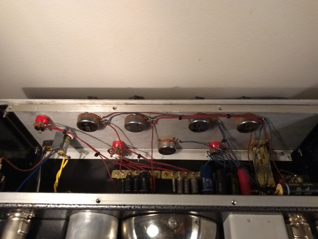
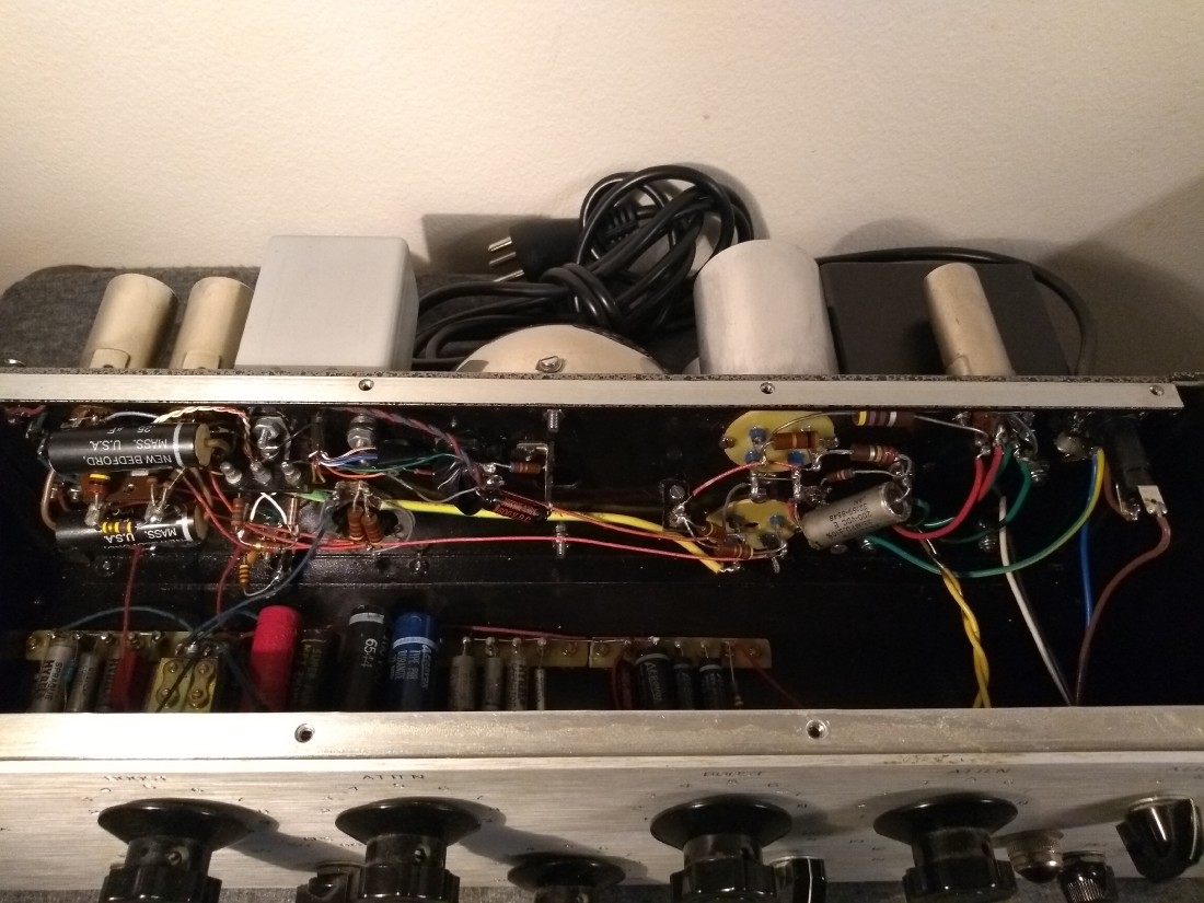
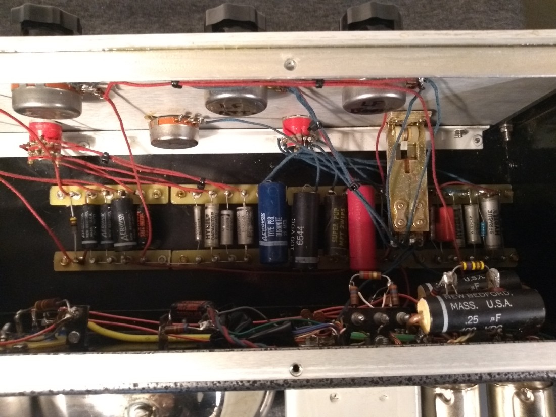
About voltage and amps Pultec 1A (pics)

GroupDIY Audio Forum

Help Support GroupDIY Audio Forum:

This site may earn a commission from merchant affiliate links, including eBay, Amazon, and others.

JMK

Active member
Joined
Feb 27, 2016
Messages
32
Location
Denmark, Copenhagen
Hi GDIY.
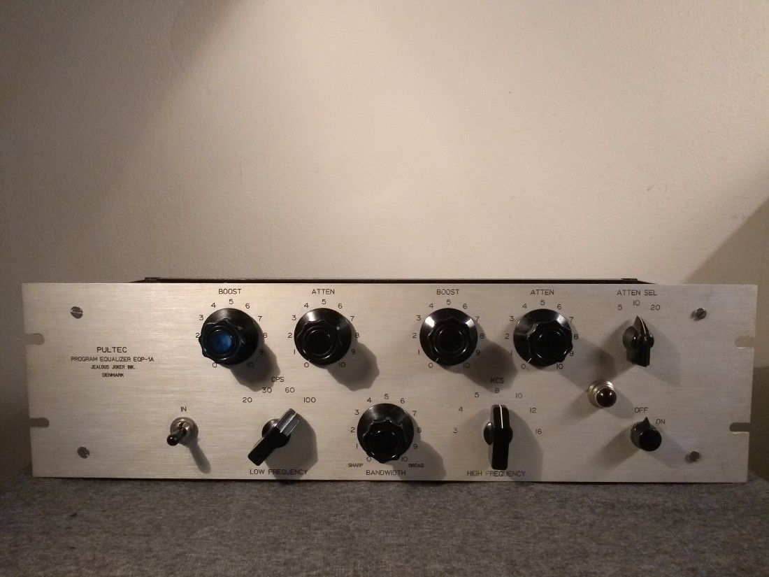
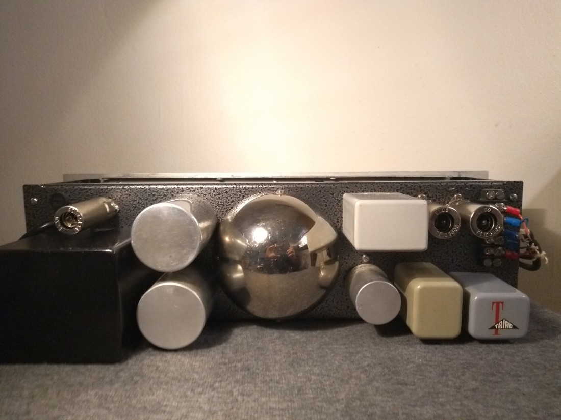
About 3 years ago i build this thing, the HF boost PEC pot went to hell, and i found out the old toroid inductor had a bad core, so while im waiting for the new inductor i did some measurements of volts, and amps in the system.

Sorry little noobish question maybe but is this correct?
When i measured the amps i took a DMM in series with the cathode on the 6X4 to the 470 ohm resistor.

I measured the volts about the 3 years ago, the old measurements were closer to the values on the original schematic.
I know the values are very close now, but im curious if this voltage change could be caused by the rectifier tube?
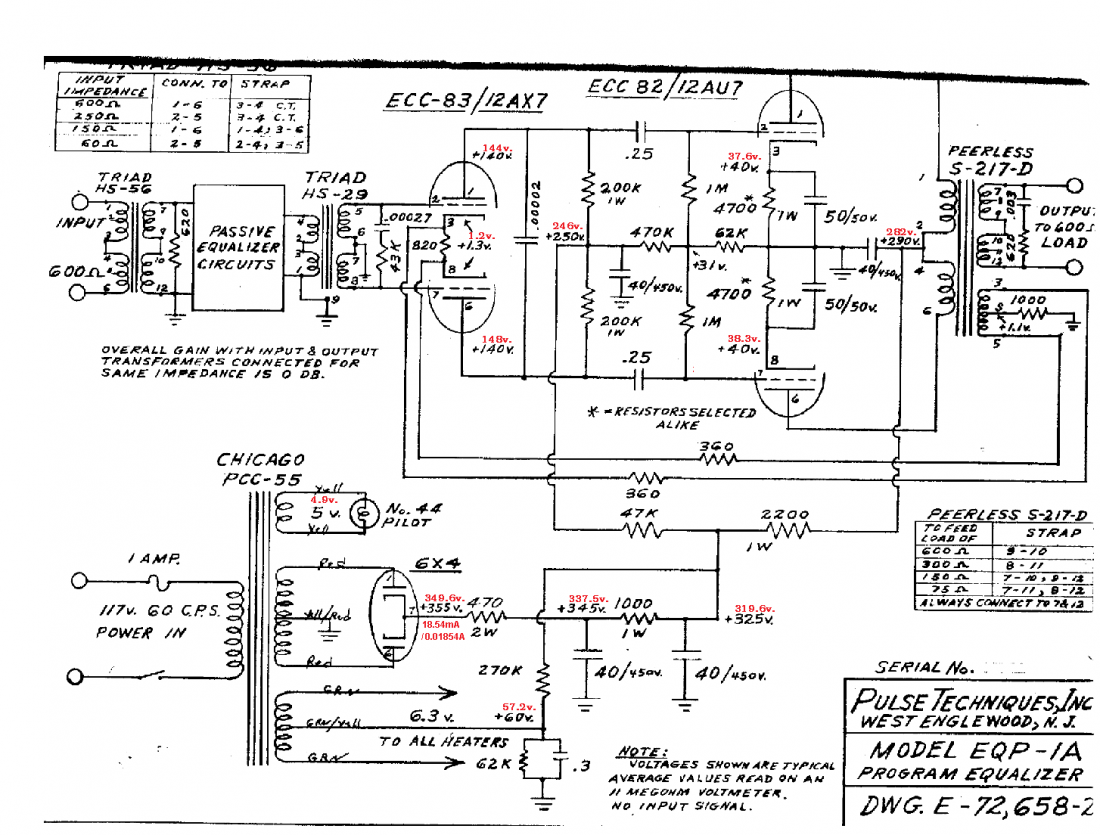
Sch-volt.png


Voltage on power-transformer and tubes.

6X4
Pin 1 = 298.7 VAC
Pin 2 = 2.7 VAC
Pin 3 = 57.3 VDC
Pin 4 = 57.3 VDC
Pin 5 = 2.5 VAC
Pin 6 = 299.7 VAC

12AX7
Pin 1 = 144.8 VDC
Pin 2 = 0.0 VDC
Pin 3 = 1.2 VDC
Pin 4 = 56.6 VDC
Pin 5 = 56.6 VDC
Pin 6 = 148.6 VDC
Pin 7 = 0.0 VDC
Pin 8 = 1.2 VDC
Pin 9 = 56.5 VDC

12AU7
Pin 1 = 277.2  VDC
Pin 2 = 26.5 VDC
Pin 3 = 37.6 VDC
Pin 4 = 56.4 VDC
Pin 5 = 56.4 VDC
Pin 6 = 276.6 VDC
Pin 7 = 26.3 VDC
Pin 8 = 38.3 VDC
Pin 9 = 56.4 VDC
1.jpg

2.jpg

3.jpg

4.jpg

5.jpg

 
The "B+" voltages look fine to me, well within 10% (or even 5%). The current, as well - 345-325 = 20V drop across that 1K resistor, as per specs, thus 20mA draw, compared to your measured 18-something. Within 10%, ie. all good.

I don't suppose you measured the mains voltage at that time, did you? It might've been a couple volts lower than the "nominal" 110V AC (which can happen in times of higher load, especially on those lower-voltage grids).

If anything, i'd swap out / "refresh" the  main electrolytics in the power supplies, simply for longevity / reliability purposes, but that's just me.
 
Khron said:
The "B+" voltages look fine to me, well within 10% (or even 5%). The current, as well - 345-325 = 20V drop across that 1K resistor, as per specs, thus 20mA draw, compared to your measured 18-something. Within 10%, ie. all good.

I don't suppose you measured the mains voltage at that time, did you? It might've been a couple volts lower than the "nominal" 110V AC (which can happen in times of higher load, especially on those lower-voltage grids).

If anything, i'd swap out / "refresh" the  main electrolytics in the power supplies, simply for longevity / reliability purposes, but that's just me.

Hi Khron, Ian
Thank  your guys very much for looking this up!
Im glad to hear it looks good.

Im running 230V AC 50 Hz to the power transformer.
Its a good question about the mains voltage, i actually didn´t measure the mains voltage at the time i did these measurements.

If you want a more precise voltage reading,
i should measure the  mains voltage when the unit is on, to figure out if mains voltage will drop?

The four electrolytic caps  are actually Sprague atoms in disguise in some motor capacitor shields  8)
the electrolytics  has the same value as the original setup.

Thanks again.


Ok, let me rephrase and condense both our answers - don't sweat it ;D

It's an audio "tone box", not a 20-digit ultra-high-precision piece of lab test equipment.

Hell, i'd be surprised if the resistors used back then were any tighter than 10% tolerance (ie. +/-10% of the nominal value = as per spec).

Keep things in perspective ;)


JMK said:
If you want a more precise voltage reading,
i should measure the  mains voltage when the unit is on, to figure out if mains voltage will drop?

The four electrolytic caps  are actually Sprague atoms in disguise in some motor capacitor shields  8)
the electrolytics  has the same value as the original setup.

Thanks again.
 
Khron said:
Ok, let me rephrase and condense both our answers - don't sweat it ;D

It's an audio "tone box", not a 20-digit ultra-high-precision piece of lab test equipment.

Hell, i'd be surprised if the resistors used back then were any tighter than 10% tolerance (ie. +/-10% of the nominal value = as per spec).

Keep things in perspective ;)

You are right, im not so good at electronics yet, but i can see what you mean, just had to be sure about this :)
 
https://www.youtube.com/watch?v=bywYBtkfsWA

One major point is made starting around 2:31 ;) (but the whole thing is worth watching)
 
Khron said:
https://www.youtube.com/watch?v=bywYBtkfsWA

One major point is made starting around 2:31 ;) (but the whole thing is worth watching)

Well this is true, approximating can be hard, and no problem can be solved exactly, is another good one.
When it comes to music its about making it sound good, and i think im ok at that, but if tweaking the circuit can make it sound even better, im in!
But i have to say i would not be able to hear the difference with -10v, not even a much larger voltage drop, well who knows it may even sound better
but i like how some of the old pultecs sound, thats why i did it in this old fashion style :)
 
Not exactly sure what's "old fashion style" with worrying about supply voltages being 1-3% off, but okay? :D

Either way, like i and Ian have said, nothing to be concerned about...
 
voltage will come up a bit as the cap comes back to full capacity.

also, 470 resistor could have drifted up if it is carbon comp,

notice measured voltage across 470 does not match measured current,
if the resistor is exactly 470 then this means there is a non DC component messing with your meter.
 
CJ said:
voltage will come up a bit as the cap comes back to full capacity.

also, 470 resistor could have drifted up if it is carbon comp,

notice measured voltage across 470 does not match measured current,
if the resistor is exactly 470 then this means there is a non DC component messing with your meter.

Hi CJ!
Do you have any new information on the original Pultec design?
Compared the old Peerless against the Cinemag?
Or do you think the Cinemag are spot on, they claim that pretty much.

Just measured the "470" carbon comp resistor and im getting 644 ohms on it.
I guess this is fine, i dont remember what i got when i first measured this resistor, but it would have been closer to 470 i think, because if it was 644 i would probably have looked it up, because im kind of paranoid and still a little new to this. ;D
Thanks!

 
CJ said:
notice measured voltage across 470 does not match measured current....

This is in the "spike wave" part of the DC supply. Most meters will NOT read this voltage correctly.

The spikes are also hard on the resistor. And before computers, this part was often under-sized. I've seen many die in a decade. This one seems to have drifted-up from "470" to 644, which means it is damaged and is probably going to fail "soon". (Probably the middle of your next perfect session.) Replace it with right value and 2X to 5X the wattage rating-- the few extra dollars are well-spent.
 
PRR said:
This is in the "spike wave" part of the DC supply. Most meters will NOT read this voltage correctly.

The spikes are also hard on the resistor. And before computers, this part was often under-sized. I've seen many die in a decade. This one seems to have drifted-up from "470" to 644, which means it is damaged and is probably going to fail "soon". (Probably the middle of your next perfect session.) Replace it with right value and 2X to 5X the wattage rating-- the few extra dollars are well-spent.

Hi PRR,
Very interesting, thanks for the tip, it will be replaced.
The 1K 1W next to it has a good reading i get 1.003K.

Yes it would be a shame if the resistor died in the middle of a good take. I only got the one in the circuit.
Its always a good idea to have replacement tubes, and some backup components for the higher voltage department i guess.


Back
Top