Alesis Microverb Service Manual or Component info

GroupDIY Audio Forum

Help Support GroupDIY Audio Forum:

This site may earn a commission from merchant affiliate links, including eBay, Amazon, and others.

lame_turtle

Active member
Joined
Apr 18, 2017
Messages
37
Hello,

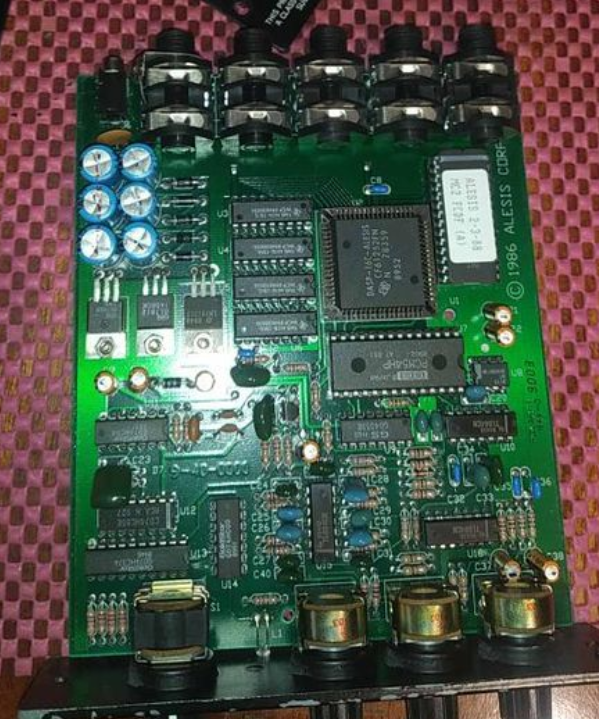
I have a microverb a friend gave me on the bench. It's the first version. I opened it and the power section is not right.
I cannot get 12v or -12v on the appropriate rails and I figured the charge pump is not working. The charge pump consists of 6 capacitors, which I'm not sure about their values because the unit is reworked. If anyone has the unit and can tell me the elctrolytic caps values, please.
Also if a service manual is available that would be great too.

Thank you very much
 
Thank you very much. I've never used a voltage doubler so I recognized it as a charge pump which I've seen several times. Still alot to learn. I just googled and this is great and really useful circuit.
I used 330uf capacitors on all 6 caps but it is still not working. The 5v regulator works ok but the +12 -12 only outputs 400mV or something. Is it the same for the diodes ? All 4001 ? (I did change the regulators, but the problem is before them since the voltage is too low .

Thank you very much for answering .
 
If there is a short after the voltage regulators, it will drop the voltages.  Cut the tracks of the +/- 12 rails after the voltage regulator and measure again.

All diodes there are 1N400x.
 
I removed the +-12v regulators completely and powered up . The input of 12v measures 7V the -12v measures 1.1V . If I have to cut the tracks I will. I just wanted to keep it nice and clean but if unavoidable ... (The input of the 5v measures 8.2V as I stated earlier.)
 
lame_turtle said:
I removed the +-12v regulators completely and powered up . The input of 12v measures 7V the -12v measures 1.1V . If I have to cut the tracks I will. I just wanted to keep it nice and clean but if unavoidable ... (The input of the 5v measures 8.2V as I stated earlier.)

I'm pretty sure this is why analogguru said specifically to cut the tracks....Just Removing the regulators won't separate the supply from the circuit ....

Sounds like it might be in the circuit unless you have something backwards or missing in the supply??.....Can't be too much in the supply to goof up though I'd imagine????

Is one of these power supplies the same????

https://groupdiy.com/index.php?topic=45697.0

The circuit is a different story I'm sure...
 
scott2000 said:
I'm pretty sure this is why analogguru said specifically to cut the tracks....Just Removing the regulators won't separate the supply from the circuit ....

Sounds like it might be in the circuit unless you have something backwards or missing in the supply??.....Can't be too much in the supply to goof up though I'd imagine????

Is one of these power supplies the same????

https://groupdiy.com/index.php?topic=45697.0

The circuit is a different story I'm sure...
/

There are only three tracks, one from each regulator plus the ground before them. These tracks go right through the regulators, that's why I supposed that removing them would do it, since there would be no connection between input and output of the regulator. Maybe I'm wrong though, it is usual :D .
 
You could check this with a continuity test??? Same here.....Instead of usually, it's often :-[

lame_turtle said:
/

There are only three tracks, one from each regulator plus the ground before them. These tracks go right through the regulators, that's why I supposed that removing them would do it, since there would be no connection between input and output of the regulator. Maybe I'm wrong though, it is usual :D .
 
scott2000 said:
You could check this with a continuity test??? Same here.....Instead of usually, it's often :-[

I did check and it is not connected another way.  Although anlogguru was of course correct and my psu has crapped out. I did build a dummy power load and the voltage of the psu drops significantly when asking for more than 50mA. I found an appropriate psu but unfortunately it is only 250mA. The microverb fired up with the new psu, dry signal works fine and the sound is crystal clear, reverb though is only a white-scratchy noise. Something is not correct in the circuit I think but can't figure what it is. =\
 
Just wondering if the schematic or service manual for the Alesis MicroVerb (the first version, 1/3 rackspace) has popped up somewhere?

Unit works fine, but the defeat-function (meant for SPDT-footswitch) doesn't - just curious how they implemented this.

Haven't traced it, but a quick Internal inspection suggests it's not some control-line into the digital realm, but that it goes to the analog part.

Thanks!
 
Hi!
I have a problem with my Alesis Microverb II (Micro not Midi)
It has wet signal dropouts and change programs by itself (is set to Med 6 it can flip it to Large or Gated Reverb program)
I check all cables off course.


I swap the power line capacitors to new one. All six (on the photo 6 blue ones) but this not helps. I read on the forum people say that caps are in the line that feed DSP chip.
I check positive on the all line stabilizators (just after the 6 blue caps. Sorry, not native English. We call them "line stabilizators")
Before caps swap, there was 5V on one of them and 11.9\12V on others.
Now all they have 12V.
I'v think that's it! Bingo!
But...
One session Reverb unit works well, but now start bugging again.

I'm not experienced with electronics a lot. But know how to solder and don't mess the polarity, so i hope i'm not a complete rookie.
But now i don't know where to search, problem.

External PSU of this reverb are have only transformer. So i think this is not the PSU.
Maybe program switching stepped pot are shorting?
I don't know.

I love this unit, it's a present from my teacher.
I'm really need it and i can't ask anybody to fix, its a long story. Please don't ask)

HELP!


I check obvious things first. All visuals are good (tracks are good with no crackles, solder points are good)
Plus, i clean PCB with pure alcohol.
Pots are scratchy (3 smooth potentiometers) but this is not the issue.
Twist them 20-30 times to clean, i work well.
In the worst situation, i can replace them.
The only pot that i can't find is the stepped "program change" pot.
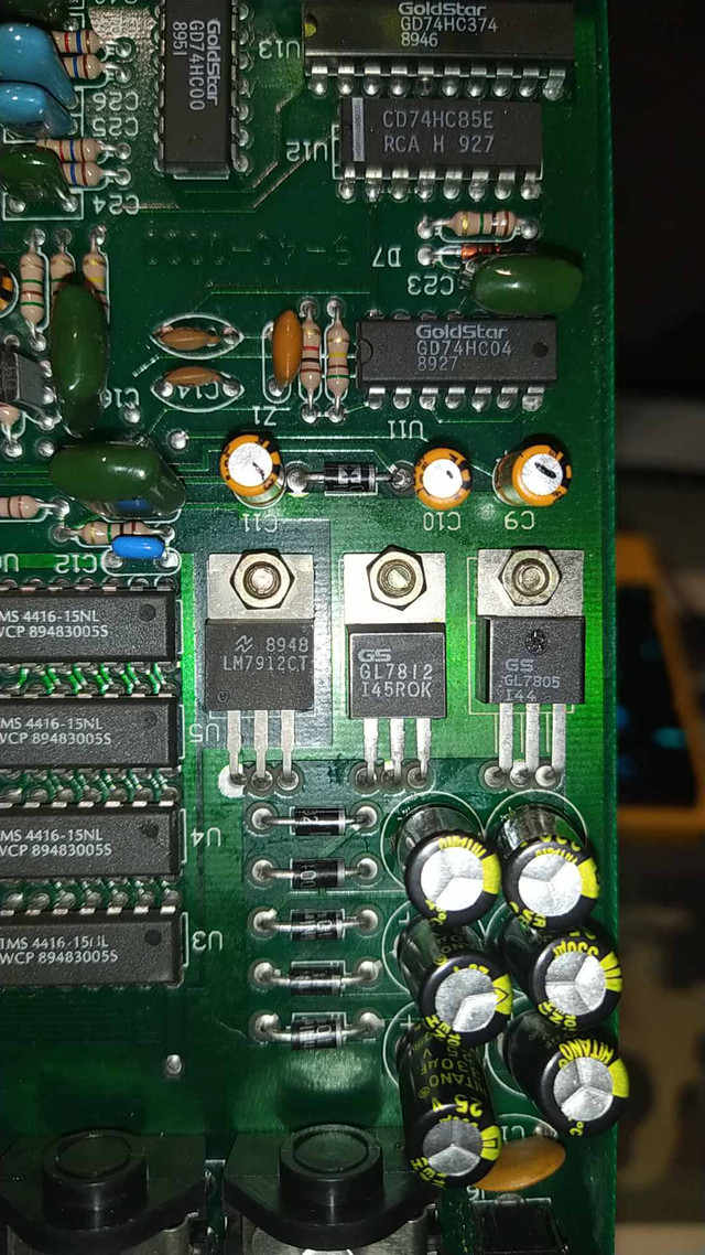
I measure today voltage on 3 "line stabilizators" aka voltage regulator
watch photos i attached in 1st post
Left to right.
1st one GL7805
~4.85 / 0 / 12.2 V (some time it drops to 11.6 V)
2nd one GL7812
~11.7 / 0 / 1
3rd one LM7912CT
~11.89 / -1 / 0
That's what my multimeter say.
 

Latest posts

Back
Top