


SSLtech
Well-known member
The GSSL seems to have evolved into one of the most 'modular' DIY projects out there... Over the years there have been several 'add-on' projects which add functionality to the unit.
The first one I remember was the Sidechain high-pass filter; there are fixed and switchable versions that I've seen. Then there was the LED meter driver; I think the 'Turbo' may have been next (to make the inter-channel detection match the original SSL limiter), then the CRC (to address the hum susceptibility of the earlier boards... now partially incorporated in the latest GSSL revisions), and the VU meter GR display driver... there are probably others that I'm overlooking.
-But to date, all the builds have still incorporated the same basic signal path; based around the NE5534 input stage and NE5532 output stage. Nice, neutral ICs with decent line drive capability at decent levels.
For my latest project, I've done what I've wanted to try for a while... an option that allows for an all-discrete API-style approach which REPLACES the entire signal path from input to output XLR's, with just a single VCA between the two op-amps. -For my particular build I used the "A"-selected THAT trimmable VCAs, to ensure that the only thing in the signal chain that isn't a discrete op-amp or an API transformer, is my most favored VCA.
This is how it's turned out:
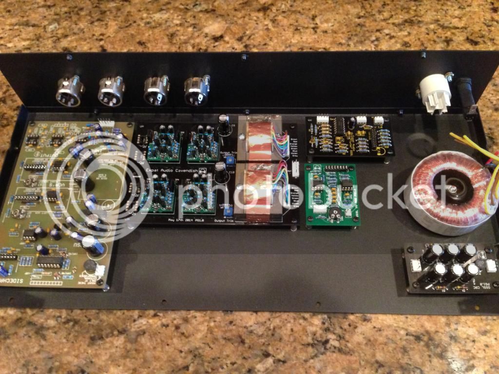
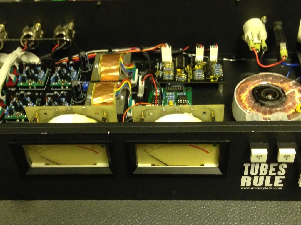
I laid out a 'test mule' based around an older 'Revision 7' board which I'd never built up... adding the Turbo (I won't build one without the Turbo nowadays!) the CRC (same) and -in this case- the VU driver, because I wanted to play with some nice metering options. (Plus I had a couple of SSL I/O module meters laying around... with VU and peak switchable ballistics, and I wanted to play with them!)
...So I gradually built the unit up...
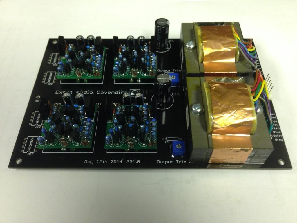
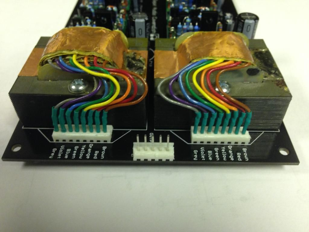
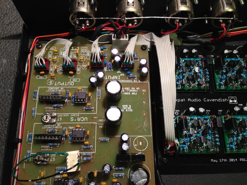
The unit basically houses the two pairs of discrete op-amps (one pair replacing the 5534 input stages, the second pair replacing the 5532 output stages and driving the transformers) and 'translates' the pinouts to 8-pin DIP sockets which are then connected to the main boards using either ribbon cables and crimp DIP plugs, or component headers soldered to ribbons, or individual wires if the builder prefers. Here's a pic showing the prototype, using ribbons soldered to 8-pin DIP headers...
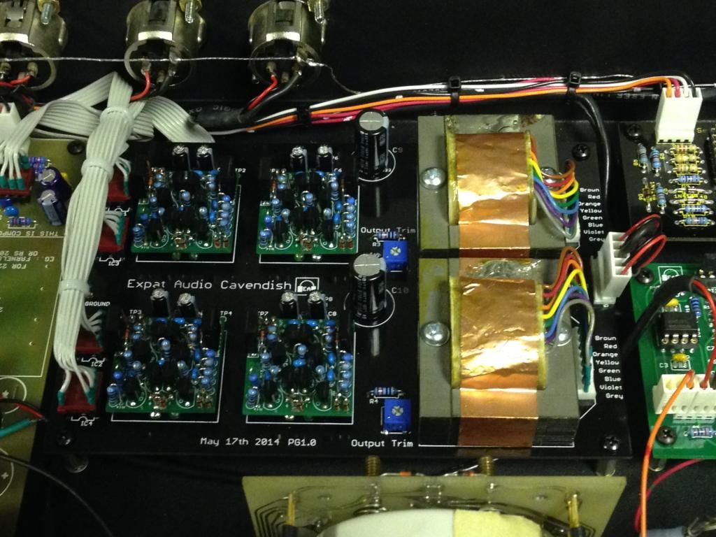
...after a bit of tidying up:
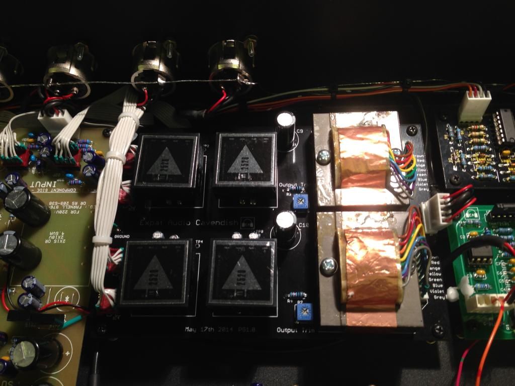
oh, and another one showing some nice API 2520 op-amps as well! ;D
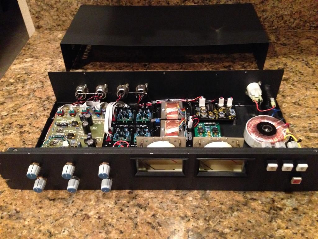
The unit finally assembled and ready for testing:
The board uses Mill-Max sockets, so I've been able to swap between a couple of different generations of API op-amps, as well as some nice 2520 clones (in this instance I built using the ML2520's from Whistle Rock Audio, but I've also plugged in a pair of Peter Purpose's 2520 clones, and all have worked stably and sounded great).
I also added a few components to make the unity gain trimmable; each channel has locations for a resistor and trim pot. The GSSL normally requires a 7.5kΩ gain set resistor, and most are built with this fitted. -You can just ignore the gain set components if you like and just use the GSSL's board locations, or remove/omit the 7.5kΩ feedback resistor for each channel on the GSSL board, and add a 5kΩ resistor and a 5kΩ trim pot (4.7k is fine for both, if 4.9 or 5k isn't readily available), then setting the trimpot mid-travel should be pretty close, but gives you the option of trimming to precision (I was fairly easily able to tweak mine within 0.01dB).
So now I've had a little while to play with it; my impressions.
None of the other 'bolt-on' projects that I've done for the GSSL have ever really been aimed at "improving" the sound, with the exception of the "ultimate GSSL" project from a few years ago... and -if you remember- while I had hoped for that to add something sonically to the signal path, I pretty quickly had to admit that it didn't really give any of the signal path improvement that I'd hoped for... even with a grand total of 34 VCAs, parallel input and output stages, and inverted signal drive etc etc etc... but despite the complexity of that build, the actual signal didn't actually sound any better. (all was not lost of course, because it led to the development of the 'Turbo' since the second sidechain did prove to be a significant operational improvement).
Anyhow hopefully you'll trust me to be objective, or at least honest enough to admit when I DON'T hear any difference... but what's my take on this?
Well, I like it. -I like it a LOT.
It's not "night and day"... but it's definitely "bigger". The low end has a pleasant 'bloom' to it. I'm presently hypothesizing that this may be something to do with the DC blocking capacitor before the primary. -Again, this is common API practice, but if anyone wants to build one and is fairly confident that their discrete op-amps are going to have a safely low DC offset at the output pin, it's easy to just install a link instead of a capacitor.
Everything fit nicely. The transformers I used were the EA2503's, and they're a lovely fit, as well as a strikingly faithful recreation of the API output transformer.
A couple of tiny wrinkles: the schematic I used on the Gyraf website contains a couple of errors, specifically regarding the 5534 output stages, and the two stages (pins 1, 2 & 3 and pins 7, 6 & 5) are transposed... so I had to wire the jumpers for the output stage with those pins swapped. Once that was done, everything was plug and play, other than one polarity swap with the output of channel 2... easy-peasy. -Will correct both of these with the next version of the board.
Output drive is nice and muscular, and there doesn't seem to be too much sonic 'penalty' if the outputs are strapped with a load resistor as a sort of 'torture test'. -I didn't try this with all different discrete op-amps, but the ML2520's (the ones I tried it with) held up and didn't appear to be particularly troubled. -The sound remained decently fat and mighty.
So, in summary: I like it. The difference is a bit like replacing "Margarine" (the IC ip-amps) with "Butter" (2520's). If anyone has a few 990's that they'd like to loan me, I'm curious to know how they behave. but initial impressions are universally positive.
Installation is intended to be plug and play. Other than the four 8-pin DIP sockets, the only connection to be made is a 0V link, which ties the ground plane and local decoupling to ground. -This can be done to any place on the unit, but ideal places would be places like pin 1 on the input socket, or any central star point, such as the 0V tie out of the transformer secondary. -Since each op-amp receives power down its associated 8-pin lead, there are test points for each op-amp's power points. -Two test points are located adjacent to each DOA, for safe and easy confirmation of power at each DOA. There's also local decoupling, since the length and cable type may vary between installations.
I'll post some more pics once I've played with it some more.
Keef
The first one I remember was the Sidechain high-pass filter; there are fixed and switchable versions that I've seen. Then there was the LED meter driver; I think the 'Turbo' may have been next (to make the inter-channel detection match the original SSL limiter), then the CRC (to address the hum susceptibility of the earlier boards... now partially incorporated in the latest GSSL revisions), and the VU meter GR display driver... there are probably others that I'm overlooking.
-But to date, all the builds have still incorporated the same basic signal path; based around the NE5534 input stage and NE5532 output stage. Nice, neutral ICs with decent line drive capability at decent levels.
For my latest project, I've done what I've wanted to try for a while... an option that allows for an all-discrete API-style approach which REPLACES the entire signal path from input to output XLR's, with just a single VCA between the two op-amps. -For my particular build I used the "A"-selected THAT trimmable VCAs, to ensure that the only thing in the signal chain that isn't a discrete op-amp or an API transformer, is my most favored VCA.
This is how it's turned out:
I laid out a 'test mule' based around an older 'Revision 7' board which I'd never built up... adding the Turbo (I won't build one without the Turbo nowadays!) the CRC (same) and -in this case- the VU driver, because I wanted to play with some nice metering options. (Plus I had a couple of SSL I/O module meters laying around... with VU and peak switchable ballistics, and I wanted to play with them!)
...So I gradually built the unit up...
The unit basically houses the two pairs of discrete op-amps (one pair replacing the 5534 input stages, the second pair replacing the 5532 output stages and driving the transformers) and 'translates' the pinouts to 8-pin DIP sockets which are then connected to the main boards using either ribbon cables and crimp DIP plugs, or component headers soldered to ribbons, or individual wires if the builder prefers. Here's a pic showing the prototype, using ribbons soldered to 8-pin DIP headers...
...after a bit of tidying up:
oh, and another one showing some nice API 2520 op-amps as well! ;D
The unit finally assembled and ready for testing:
The board uses Mill-Max sockets, so I've been able to swap between a couple of different generations of API op-amps, as well as some nice 2520 clones (in this instance I built using the ML2520's from Whistle Rock Audio, but I've also plugged in a pair of Peter Purpose's 2520 clones, and all have worked stably and sounded great).
I also added a few components to make the unity gain trimmable; each channel has locations for a resistor and trim pot. The GSSL normally requires a 7.5kΩ gain set resistor, and most are built with this fitted. -You can just ignore the gain set components if you like and just use the GSSL's board locations, or remove/omit the 7.5kΩ feedback resistor for each channel on the GSSL board, and add a 5kΩ resistor and a 5kΩ trim pot (4.7k is fine for both, if 4.9 or 5k isn't readily available), then setting the trimpot mid-travel should be pretty close, but gives you the option of trimming to precision (I was fairly easily able to tweak mine within 0.01dB).
So now I've had a little while to play with it; my impressions.
None of the other 'bolt-on' projects that I've done for the GSSL have ever really been aimed at "improving" the sound, with the exception of the "ultimate GSSL" project from a few years ago... and -if you remember- while I had hoped for that to add something sonically to the signal path, I pretty quickly had to admit that it didn't really give any of the signal path improvement that I'd hoped for... even with a grand total of 34 VCAs, parallel input and output stages, and inverted signal drive etc etc etc... but despite the complexity of that build, the actual signal didn't actually sound any better. (all was not lost of course, because it led to the development of the 'Turbo' since the second sidechain did prove to be a significant operational improvement).
Anyhow hopefully you'll trust me to be objective, or at least honest enough to admit when I DON'T hear any difference... but what's my take on this?
Well, I like it. -I like it a LOT.
It's not "night and day"... but it's definitely "bigger". The low end has a pleasant 'bloom' to it. I'm presently hypothesizing that this may be something to do with the DC blocking capacitor before the primary. -Again, this is common API practice, but if anyone wants to build one and is fairly confident that their discrete op-amps are going to have a safely low DC offset at the output pin, it's easy to just install a link instead of a capacitor.
Everything fit nicely. The transformers I used were the EA2503's, and they're a lovely fit, as well as a strikingly faithful recreation of the API output transformer.
A couple of tiny wrinkles: the schematic I used on the Gyraf website contains a couple of errors, specifically regarding the 5534 output stages, and the two stages (pins 1, 2 & 3 and pins 7, 6 & 5) are transposed... so I had to wire the jumpers for the output stage with those pins swapped. Once that was done, everything was plug and play, other than one polarity swap with the output of channel 2... easy-peasy. -Will correct both of these with the next version of the board.
Output drive is nice and muscular, and there doesn't seem to be too much sonic 'penalty' if the outputs are strapped with a load resistor as a sort of 'torture test'. -I didn't try this with all different discrete op-amps, but the ML2520's (the ones I tried it with) held up and didn't appear to be particularly troubled. -The sound remained decently fat and mighty.
So, in summary: I like it. The difference is a bit like replacing "Margarine" (the IC ip-amps) with "Butter" (2520's). If anyone has a few 990's that they'd like to loan me, I'm curious to know how they behave. but initial impressions are universally positive.
Installation is intended to be plug and play. Other than the four 8-pin DIP sockets, the only connection to be made is a 0V link, which ties the ground plane and local decoupling to ground. -This can be done to any place on the unit, but ideal places would be places like pin 1 on the input socket, or any central star point, such as the 0V tie out of the transformer secondary. -Since each op-amp receives power down its associated 8-pin lead, there are test points for each op-amp's power points. -Two test points are located adjacent to each DOA, for safe and easy confirmation of power at each DOA. There's also local decoupling, since the length and cable type may vary between installations.
I'll post some more pics once I've played with it some more.
Keef
")