Another HT Voltage Regulator

GroupDIY Audio Forum

Help Support GroupDIY Audio Forum:

This site may earn a commission from merchant affiliate links, including eBay, Amazon, and others.

guavatone

Well-known member
Joined
May 21, 2005
Messages
1,609
Location
USA
I am trying to figure out how to fudge this reg circuit dowwn closer to 290VDC. The article says to take out one of the PNP transistors to get less than 300V. It looks like it shouldn't be to hard, I just cant seem to wrap my head around the theory though.

-looks like this is backwards -from diode bridge on right.
simple%20ss%20series%20regulator.png


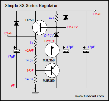
The article his here:
http://www.tubecad.com/2006/11/blog0087.htm

Any help would be greatly appreciated.

PS- I bet no one can guess what this is for.
 
Vout=(10/1k)*(1k+14k5+14k5)=300V

To get Vout=290V, change 14k5 resistors to 14k/2W

or put the 33k resistor in parallel to the 1k.

Regards,
Milan
 
Ignore the advice about removing any transistors to change the voltage.

The output voltage is essentially the voltage developed across the two 14.5K resistors when passing the current developed by the 1k resistor, across 10v zener drop. So 10 mA across 29k is 290V + the zener's 10v =300v

To reduce the output 10v reduce the 29k resistance by 1k to 28k... You could put a large value trim pot across the two resistors or swap out one of the 14.5ks for a small pot and new resistor that adds up to approx 14.5k if you need to adjust it.

JR
 
Thanks Everyone.


I took down the 47uF caps to 10uF since I am not sure if they are there for decreasing ripple and my other big caps are taking up much space. Is that OK? Are the 47uF(C4 and C3) caps needed at all with my smothing and RC section?

This should be fine with 60 mA load right?

290v-psu-2.jpg


moamps, 33k? :?
 
Is 10uF OK for C4?

I though C5 would be good for additional smooting and power reserve. I think the 2 preamps this is powering will have small 10uF/400 caps before and after the tubes (dual triode and pentode). So maybe the latter will be enough.

Thanks John, your input really helped me understand this regulator better.
 
[quote author="guavatone"]
moamps, 33k? :?[/quote]

Hi,
I'm sorry, I've made a mistake in articulating the idea.The R3 should be increased (not decreased) by 3% to get lower output voltage. This means that the output voltage will decrease by 10V if we insert a 33ohm resistor in series with the 1k resistor (R3), provided that the R4 and R5 remain 14k5. At least this is how it works in theory.

In practice, resistors have a certain level of tolerance. Thus, if you already have a 1k resistor with 5% tolerance in your parts bin, it may turn out to be just the thing you're looking for (i.e. it may have a resistance of 1033 ohm).

Anyway, I would suggest some minor modifications to the original schematic. R4 and R5 in the original design have values which are not easily obtained, they are rated to 2W minimum and have 1% tolerance. I propose the use of standard 15k/3W for R4 and R5 instead. In this case, the R3 would also have to be replaced with a 1k5 resistor in parallel with the series connection of a 1k resistor and a 10k trimmer. The 10k trimmer here is used to fine-tune the output voltage.

Also, if possible, keep the Q1 and Q2 in thermal connection to minimize the output voltage drift that may occur when the output transistor heats up.

Regards,
Milan
 
Thanks Milan. Wow I didn't realize the limited vaues at 2W. I was originally thinking 1/2W but I guess 2W is better at this voltage.

I finally figured out simulation in Proteus and came up with this schemo. I am not sure if I got moamp's pot/resistor section right. I had a 10K and lowered to 1K because it wasn't getting there. Should i be concerned with the trimmer pot rated at 1/4-1/2 Watt?

290v-psu-4.jpg
 
[quote author="guavatone"]
I finally figured out simulation in Proteus and came up with this schemo. I am not sure if I got moamp's pot/resistor section right. I had a 10K and lowered to 1K because it wasn't getting there. Should i be concerned with the trimmer pot rated at 1/4-1/2 Watt?
[/quote]

Hi Charlie!

You should disconnect R2 from the slider of the RV1 pot and connect it to the Q2 base-R5 junction. Use 10k trimmer for RV1. 1/4 Watt should do just fine, I wouldn't worry about it.

Regards,
Milan
 
This place for a trimmer is better than proposed by me in my previous posting (in case of lost contact output voltage will go down).
 
Cool. I updated the schemo above with the corrections.

here are resistor specs I found through mouser:

R3 and R4 =3W 1% Vishay/Dale wirewound

R4 and R5 = 3W 1% Vishay/Dale wirewound or 3W Metal oxide(cheaper)

The dales are pretty expensive but seem like a good way to go in order to keep tolerances tight.

Should all the transistors be heatsinked? I know the tip50 should, I'm not sure about the MJE350's. I am not sue what you mean by keeping Q1 and Q2 in thermal connection. -heatsink both?


BTW, I tried a simulation on a ckt I found in Morgan Jones' Valve Amp Book on pg 361. It uses a 317 reg and it seemed to be all over the place. The sim on the ckt above was pretty tight though.
 
[quote author="guavatone"]
R3 and R4 =3W 1% Vishay/Dale wirewound
R4 and R5 = 3W 1% Vishay/Dale wirewound or 3W Metal oxide(cheaper)

The dales are pretty expensive but seem like a good way to go in order to keep tolerances tight.
Should all the transistors be heatsinked? I know the tip50 should, I'm not sure about the MJE350's.[/quote]

Good work, Charlie.

R3 may be 0.5W 5% metal oxide;
R4 and R5 may be 3W or 5W 5% metal oxide.

Higher resistor tolerances are not an issue here since you will be able to set voltage to the desired value with a trimmer. No fancy and/or overpriced parts required.

Heatsinks are not mandatory for MJE350's.

Regards,
Milan
 
Back
Top