API 312 Thread!

GroupDIY Audio Forum

Help Support GroupDIY Audio Forum:

This site may earn a commission from merchant affiliate links, including eBay, Amazon, and others.
Hi.

I built the 312 with CM75101APC Input and 2503 Output.
No servo-parts and no unbalanced parts used. I've got either a selfbuilt Melcor, an original 2520 or 5534 ICs. But any of them just reproduces a heavily distorted input signal. It sound just like I'm talking through a guitar distortion pedal. :evil: You can hear my talking through it, so i think its not a problem with the different opamps. It's just heavily distorted. I checked all the board for possible problems but could not find any.

Anyone got a solution for this, please?
 
[quote author="Benny"]Hi.

I built the 312 with CM75101APC Input and 2503 Output.
No servo-parts and no unbalanced parts used. I've got either a selfbuilt Melcor, an original 2520 or 5534 ICs. But any of them just reproduces a heavily distorted input signal. It sound just like I'm talking through a guitar distortion pedal. :evil: You can hear my talking through it, so i think its not a problem with the different opamps. It's just heavily distorted. I checked all the board for possible problems but could not find any.

Anyone got a solution for this, please?[/quote]

This sounds like a lack of an 0V reference to the circuit. How are have you connected your Pin1's on the ins/out of the XLR connectors? Also have you tied the OV of your PSU to ground as well?

You need to make sure you tie them to the chassis, so a piece of wire goes from Pin1 on the input and output XLR's to the XLR screw on the chassis for the audio part.

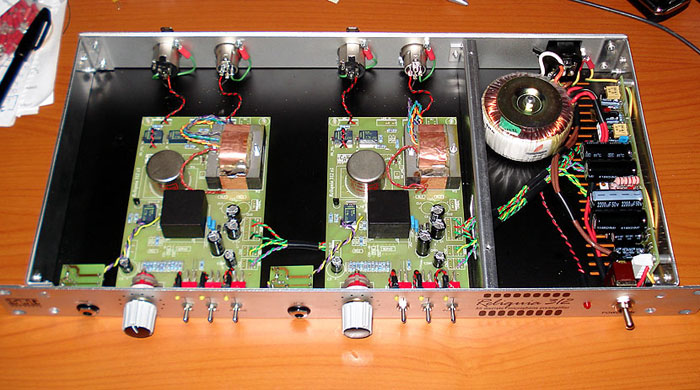
On the power side you need to make sure either the input or output 0V is referenced to Ground as well, I normally take the PSU output 0V and tied it to my star ground point near the IEC inlet, here is a pic of my newly built unit for reference.

R312_Racked.jpg


Cheers

Matt
 
Hey Matt,

You've never run into problems with the Pin1's being grounded to different positions on the chasis, ie. not star grounding??

There seems to be a million different philosphies on the whole grounding scheme.

How's the studio going? I picked up a copy of "The Art of Electronics", it's fantastic, great read, thank you!
 
Hey Matt.

I've got ground wire from IEC power inlet to a screw on the chassis. At that screw the other ground wires from pins 1, from the PSU and from main PCB meet. But I don't think it's a grounding issue. I don't have any humming sound. It sounds more like the opamp is distorting heavily. It has to be something in the gain section, I think. I checked and rechecked all resistor and cap values. Seem to be right. :?

Ben
 
My PSU is outside the box in another box.
take it trough 5 pins XLR to the Pres and ground directly from XLR to star ground in the pre's box.
Run every pin 1 trough separate wires to Star ground. run every electronic ground separate too, 9V ground, 48v ground and +/- ground .

Benny i had distortions on mine but only when 48V engaged.
I re-did the 9V wiring. took R11 and put a wire instead. solder after C1 instead of before the 48V regulator! i was using a 22-0-22 transformer and change it to a 18-0-18.

hope it helps.
 
[quote author="Sender"]Hey Matt,
You've never run into problems with the Pin1's being grounded to different positions on the chasis, ie. not star grounding??
[/quote]

Hey Will,

Nope, I do all my pres this way, I think I saw it in the RANE notes once and it has worked well for me since.

[quote author="Sender"]How's the studio going? I picked up a copy of "The Art of Electronics", it's fantastic, great read, thank you![/quote]

RE the studio, I took the old roof and ceiling out last week, going to raise it just over a foot for bit more height and also adding some more mass to the live room for better isolation... should be ready to move in gear end of next week... if the the contractors are on target....

I'm glad you are enjoying the book, well worth the investment.

But I don't think it's a grounding issue. I don't have any humming sound. It sounds more like the opamp is distorting heavily.

Yes, grounding wasn't the right word, which is why I said it is missing a reference for 0V... I've had this happen before when I built Fabio's FETboy's and only once I made sure the Pin 1's were seeing 0V did it work... have you triple checked continuity between your ground/0V points?

Cheers

Matt
 
Hey Matt.

I triple checked all ground/0V connections. Everything seems to be right and properly connected to boards, chassis and IEC. It still sound horrible if you speak into that microphone. Like through a distortion pedal.
I really don't have a clue now.
 
Post a pic of one of the boards and I'll take a look over it for you, sometimes it is good to have a fresh set of eyes. Hang in there... we will get to the bottom of it :thumb:

Matt
 
Hi Benny,

It looks like your R1 value is 30K and the schematic and parts overlay I have calls for 20K. Since it is in the feedback section of the amp block it might account for the distortion as you have an extra 10K there in addition to your existing gain resistors (RG1-RG12).

Cheers

Matt

P.S RE the pic, prob better to link to it rather than embed it into the page.
 
Hi Mat.

I had R1 20k before but I changed it to 30k. I thought it would perhaps lower the gain of the opamp. But it sounds the same with 20k and with 30k.

Perhaps lower it a bit? Lets say to 10k?
 
Hey 3nity.

I had CD1 and CD 2 on board yesterday. I took them out just to test around a bit if the distortion changes in some way. But unfortunately it didn't.
 
I read in this thread that one could leave out RC and CC if using a CM75101APC as input and with it you have to change RL from 100k to 150k.
 
[quote author="Benny"]I read in this thread that one could leave out RC and CC if using a CM75101APC as input and with it you have to change RL from 100k to 150k.[/quote]

Correct. With that Cinemag a Zobel Network (RC+CC) is not required.

Cheers

Matt
 
Benny, check out the output transformer - may be they changed the colors over the time, and yours is a very old one.
I don't have the same type (with the thicker leads) anymore here,

but ohm out brown to orange ...
 
Yea, I see.

I've got a different color coding on the output-tranni wires.
Maybe it could have to do something with this?!?
I'll check around a little bit.
 
Are you sure your 1731 is correct? Looks like you used series connceted resistors as substitutes in several places. I know the 1731 threads are long (and confusing), but it looks like you missed two "fixes" that are needed and maybe one that makes the 1731 happier in the 312 circuit:

1) D2 is a double diode (two diodes in series, both with the same polarity so you get a 1.3V total drop across them)
2) C2 should connect to - in rather than the base of Q3. Simply pop out the leg closest to the - in pin and connect it to the stub of the pin that sticks out on the top side of the PCB. It might be easier to pull C2 and replace with a new on leaving one lead long enough to connect directly to the top of the - in pin (that's what I did).
3) The 1731 wants more compensation C than is present on the 312 main board (C5 on Fabio's schematic). You don't want to mess with C5 as this will compromise your ability to use other op-amps. The solution is to solder an additional 100-120pF cap to the bottom of the 1731 board between the out and - in pins. Use spaghetti tubing to keep the long leads from shorting against other traces and use a small cap mounted flush against the board so it doesn't interfere with anything when you plug it in.

I think #1 is the main cause of your problem unless there is something wrong with your gain switch or gain resistor values.

A P
 
Back
Top