balanced ins and outs

GroupDIY Audio Forum

Help Support GroupDIY Audio Forum:

This site may earn a commission from merchant affiliate links, including eBay, Amazon, and others.

briomusic

Well-known member
Joined
Mar 1, 2009
Messages
411
Location
London/Berlin
i am trying to add balanced input and output to a little circuit i am working on.
the input i borrowed from the calrec eq and the output stage is a THAT 1646.
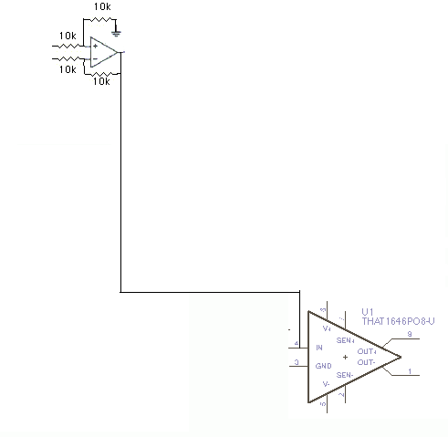
for testing I just connected the output of the unbalancing op-amp to the input of the THAT chip:
symm.gif

this results in a very quiet and hissy signal. why?

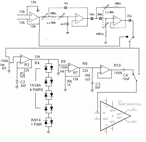
the finished circuit is going to be this:
briosatt1.gif

how do I reduce the level to compensate the 6dB boost of the 1646?

thanks!
 
thanks abbey road, the ground was connected but i forgot the "sense" inputs. strangely it worked that way earlier in a different configuration. also managed to come up with a voltage divider to bring the 1646 back to unity gain. just the filters to go now....

chrioN: tape sat sounds great, going to mess around with a few parameters to see how i like it best.
 
briomusic said:
how do I reduce the level to compensate the 6dB boost of the 1646?
Done easiest in the debalancing stage (double value Rin or half value Rfb and Rshunt). A THAT1206 or SSM2143 will come with matched resistors for improved CMRR.
BTW, the LPF section is missing a series resistor in front of the 1st of th 2x100K (lin.) pot.
Is getting hold of the 2x100K (rev.log) pot worth the trouble or will you substitute it with some switched resistors in the HPF section?
 
ChrioN said:
ze tape saturator. When done, please tell us if its usable!

I had this on a test board once and it didn't sound too bad. Whether it's "tape" saturation is more than debatable, of course, but usable for creative sound shaping (fuzz). Though I ended up running it in parallel with the clean signal when I tested it -- in order to not lose too much of the original sound quality, and also slightly tuned EQs on both signals: clean & sat simulator. This turned it into something more like a low freq exciter...
 
I agree with Script's review of the sound of this circuit. Personally, I love it, and it helps boosting 'perceived' volume, which is what pop/radio music is all about isn't it  ::)

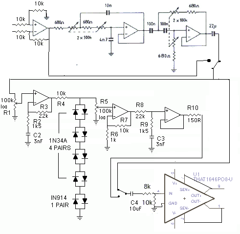
Harpo, I don't want to reduce the level before the tape sat circuit, as this will mess with the gain staging. Thanks for teaching me how it's done anyway! I ended up experimenting with a voltage divider just before the 1646 and managed to ruffly match the levels (in a glorified fuzzbox, what's a few 1/10 dB between friends).
briosatt1-2.gif

Thanks also for pointing out the additional series resistor which 'they' tried to hide from me in the original schematic. Good point about the stereo rev log, I hate unobtainium components. might just go with a normal log and reverse the direction (i.e. clockwise = more filtering). Alternatively do the whole thing with switches for easier stereo usage. This is why it's called the drawing board  :D
 
briomusic said:
Harpo, I don't want to reduce the level before the tape sat circuit, as this will mess with the gain staging. Thanks for teaching me how it's done anyway! I ended up experimenting with a voltage divider just before the 1646 and managed to ruffly match the levels (in a glorified fuzzbox, what's a few 1/10 dB between friends).
Doubling the 22K feedback resistor value in your saturator gain stage will make up the 6dB loss for same drive, assuming your opamp can do this voltage gain of 30.
From THAT1646 datasheet, "..must be driven by a low impedance source, preferably directly from opamp outputs, to maintain the specified performance". Your 8K series from your 8K/10K attenuator might be contraproductive with double parts count.

... which 'they' tried to hide from me in the original schematic...
This is not the only one. C2 in the shunt arm from the saturator schematic probably isn't a 3nF cap ;), but if you like it as is ...

just my 2ct
 
Thanks again Harpo, I have given this some serious thought and tried out all the options:
option a: reducing gain at unbalancing stage - disadvantage: small signals don't drive into saturation, even with R1 fully turned up and R4 removed.
option b: doubling R8 to 44k - works for tape sat, but not if tape sat is in bypass and only filters are used.
option c: voltage divider before balancing chip - "affects performance" - but in what way? Is the 8k adding to the output impedance of the tape sat or the input impedance of the balancing chip? (I never understand that bit). Would it be better to have smaller values, i.e. 4k and 5k? I would still prefer to get this version working as it works in any configuration (only filter, only tape, both).

also....what's wrong with C2 being 3nF? according to this: http://home3.netcarrier.com/~lxh2/tapesat.html it is part of the (2.25kHz) emphasis/de-emphasis applied by R2/C2 and R9/C3?
 
briomusic said:
option a: reducing gain at unbalancing stage - disadvantage: small signals don't drive into saturation, even with R1 fully turned up and R4 removed.
option b: doubling R8 to 44k - works for tape sat, but not if tape sat is in bypass and only filters are used.
With -6dB loss in your unbalancing line receiver, without your 8K/10K attenuator and +6dB gain from THAT1646, there should be unity gain in tape sat bypass mode as well.
I wasn't talking R8 but R3 for same drive. This is a non-inverting bandwidth limited gain stage with voltage gain of 1+R3/R2 in the pass band, giving 15.67 or +24dB. If you subtract 6dB from input side, doubling R3 will make up this 6dB loss if your opamp can do so. A 22pF-33pF cap across this feedback resistor might help oscillating if required. Compression starts when signal exceeds the ~4.6V from the 4 germanium+1 silicone diode drops, so with current limiter/voltage divider R4 10K and R5 100K you'll need about 5V at 1st opamp output before compression takes effect.

option c: voltage divider before balancing chip - "affects performance" - but in what way? Is the 8k adding to the output impedance of the tape sat or the input impedance of the balancing chip? (I never understand that bit). Would it be better to have smaller values, i.e. 4k and 5k? I would still prefer to get this version working as it works in any configuration (only filter, only tape, both).
Your 8K/10K attenuator with chips 5K input impedance in parallel to your 10K shunt actually drops signal by 10dB. A 3.3K instead of 8K might be a better fit if you keep your gain staging as drawn.
From equivalent circuit diagram the THAT1646 internally has differential inputs, connecting thru 5K resistors to the outside world. The inverting input already has one side of these 5K resistors internally connected to gnd, so any different value greater than zero ohm in front of the non-inverting input will degrade CMRR and as follow up the chips ability to supress longitudinal errors OCMR. Your 18K attenuator, consisting of a 8K series and 10K shunt resistor will increase the internal 5K, connecting to non-inverting input to 13K and the chips input impedance of 5K is reduced by paralleling your 10K shunt resistor.

also....what's wrong with C2 being 3nF? according to this: http://home3.netcarrier.com/~lxh2/tapesat.html it is part of the (2.25kHz) emphasis/de-emphasis applied by R2/C2 and R9/C3?
Sorry, nothing wrong with C2. R2/C2 is a HPF with 6dB/oct rolloff set for 35kHz. Voltage gain of this non-inverting stage will always be greater than 1, so with 6dB/oct slope this stage increases gain above 2.262 Hz, close to perfect for tape rollover frequency 0/2274Hz for IEC standard 7 1/2 ips. Use 1.5nF for C2 and C3 for 0/4547Hz IEC 15 ips simulation or 2.2nF for C2 and C3 and 33nF in front of R1 for 50/3180Hz NAB standard 7.5 and 15 ips.

I could be wrong though.
 
Harpo said:
Compression starts when signal exceeds the ~4.6V from the 4 germanium+1 silicone diode drops...

Yeah, I've got this circuit built up on protoboard and found this to be an issue. It takes a very hot signal to get into limiting. No problem for any of my DIY preamps, but used in a mix even with a kick drum track recorded fairly hot on peaks I needed to boost the signal in PT to get any clipping action.

I'm considering adding a switch to short the top pair or two pairs of Ge diodes to lower the clipping threshold for softer signals. That would also change the Si/Ge blend for a different saturation characteristic. I also want to try the various resistors strapped from the top of the diode tree to nodes. I can't find the schematic online at the moment, but it consists of a 47k R across the top pair of Si diodes, a 68k across the top two pairs, a 120k across the top three pairs, and a 270k across four pairs. It appears that would feed some small portion of the signal voltage to the Ge diodes, and thusly biasing them on at a lower input signal voltage.

BTW, running mine completely unbalanced, so I'm sacrificing -6dB on the way in. Maybe I'll add the balanced receiver stage a transformer on the input.
 
hi skipwave, i think you are referring to this schematic:
http://7527097470863791245-a-1802744773732722657-s-sites.googlegroups.com/site/doorstopelectronics/limiter_modified_1.gif?attachauth=ANoY7craRd6Z1Tixh6l1pAz6mqN6vDLEcqJ7347v0JfmrsVSwIyjYHPtypXYk7ki4ErN1FC0ndpgTLweREGxasUGuXKOsnFhNrDIkrHqUtI67UZlGu4aEwQGWEoWfXYzFyoSdLs9e2sjVrJP-dv0DaNs4p4V2xiSdV4qZCGbHwC6EI0HdL4rcWv2GChbjqOC5OkUVKizS2COrhtYrIhagkKlw3nTz5Cjtw%3D%3D&attredirects=0
I found the resistors to have very little effect, and I dont really want to soften the effect in the first place, so I am not going to bother. I did however try bypassing pairs of diodes and that really helps getting the "threshold" down. leaving only the silicon diodes turns it into a fuzzbox :)

to get your signal closer to the threshold, can't you change R3 and/or R4?

cheers
briomusic
 
Sure, that's one way. Add more gain up front. Diode clipping is such a crude method of limiting that an elegant solution to gain staging would be so much guilding.

I tested the forward bias of each diode and found that the Ge are, as expected, less consistent that the Si specimens. I wondered briefly if the large diode tree was really about the blend of clipping characteristic (Ge v. Si) or more about averaging out variations in turn-on volts to maintain symmetrical clipping. For the cost of a cheap toggle switch, I'll mess with shorting diode pairs.

That's interesting that you didn't hear much difference with the resistors installed. They are of high value relative to R4, so I wouldn't expect anything drastic, but some change none the less.

Thanks for sharing your observations, and your I/O balancing scheme.
 
Back
Top