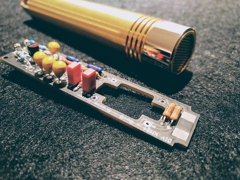
Banzai's KM84 DIY Body & PCB kit build thread

GroupDIY Audio Forum

Help Support GroupDIY Audio Forum:

This site may earn a commission from merchant affiliate links, including eBay, Amazon, and others.
...and here is where I am attempting to check signal at fet drain which also is the junction of C2, C4 and R4. I do not seem to be reading anything with my scope. I have double checked scope operation by referencing the injected signal. I have tried this with phantom power applied and not. 48v does not seem necessary for this calibration. I have built 2 of these mics and each is the same. I thinik I am either making a silly mistake or my FETs are no good. Seems odd that 2 would be bad, but I did buy "real" 2N3819s off eBay from someone in the UK. Any ideas?
 

Attachments

  • scope signal at FET drain.jpg
    scope signal at FET drain.jpg
    1.5 MB
Ruud give an advice at the white market, you can’t bias it like a U87, I remember that he told, that’s capacitor is needed for.
Maybe he can tell us something about the biasing again.
 
I am not shure, but i think you have to feed the signal into the coupling cap c1.
So you can go to the capsule terminal.

To the CM-5722: Can i cut the Whi/Brn  Whi/Red and the Whi/Blk Whi cable or do i have to connect them ?
 
will there be another batch of these. I remembered there was talk about that. ;)
I would love 2 of these!
 
White Market thread is open!

https://groupdiy.com/index.php?topic=68360.0

GDIY-KM84.jpg
 
Hello, everyone,

Just in case the White Market thread disappears with information like calibration, I thought I would post it here for safe keeping. Many thanks to RuuDNL for originally providing this procedure:

"Connect a signal generator through a capacitor (~1000 pF) to the gate of the FET. 1Khz or so is fine.
Replace the source resistor temporarily with a 10 K.ohm trimpot.
Increase the level of the signal generator until you get distortion (oscilloscope or distortion analyzer).
Adjust the trimpot for lowest distortion and symmetrical clipping.
Measure the value of the trimpot and replace the trimpot with a fixed resistor with the value you measured.
That's it
!"

And a further explanation:

"Just connect the capacitor to the 'pin' that connects to the capsule.
The audio generator signal feeds to the (not connected) side of this capacitor.  (And the ground wire of course.)
The capacitor is to separate the polarisation voltage. You don't want +46 V or so on you signal generator!
If you don't have an oscilloscope or a distortion analyzer, you can also do this by ear.
Turn the trimpot slowly until minimal distortion (on a sinewave) is heard.
Then increase the level of the signal level, and adjust the trimpot again.
Of course you need to connect the XLR to an amplifier!
"

Thanks!

Paul
 
Hey guys, I’m wanting to pull the trigger on a couple of these, but I don’t own or have access to an oscilloscope, so I’m a bit concerned at how I would calibrate. Anyone have a guide on a work-around?
 
adam.schw said:
Hey guys, I’m wanting to pull the trigger on a couple of these, but I don’t own or have access to an oscilloscope, so I’m a bit concerned at how I would calibrate. Anyone have a guide on a work-around?

Read the above post again. All the way through this time....


Thanks!

Paul
 
Hi Peeps,

It's been a while coming, work, kids, life, fishing, etc... but here's a .pdf build guide to help everyone out with getting their mics together. It's talking to the newest DIYer but hopefully it'll be a handy way for anyone to get stuck into the fun without too many headaches!

http://bit.ly/2ML5aOv

Rock On!

Graeme
 
GraemeWoller said:
Hi Peeps,

It's been a while coming, work, kids, life, fishing, etc... but here's a .pdf build guide to help everyone out with getting their mics together. It's talking to the newest DIYer but hopefully it'll be a handy way for anyone to get stuck into the fun without too many headaches!

http://bit.ly/2ML5aOv

Rock On!

Graeme

Thanks for the build guide. I think that the one thing I didn't see is that the opening for the transformer is a bit small. I had to file the opening bigger to get mine to fit. This should be done first, before populating the pcb with components so leads aren't potentially broken. This might make life a bit easier. Check to see that it fits first, before populating.
 
Just a comment about one of my mistakes hopefully to help others:

My signal generator defaults to 10kHz and 10Vpp when starting and this appears to burn out the 2n3819 in circuit when attempting biasing. That issue combined with a couple faulty transformers have caused me some significant troubleshooting time, but golly gee... I'm getting better at this DIY thing.
 
Jim50hertz said:
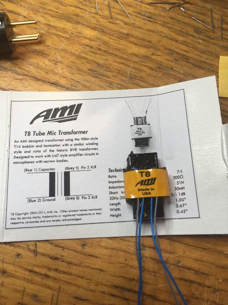
Anyone who has used the AMI T8 transformers have any clues as to which wire is which here?

Is that how they are supplied?

If you have a DMM set it ohms and measure blue to blue and grey to grey first to check it. Blues should be higher resistance

Next test for the polarity will need signal generator and a scope you will need to look at the output and compare it to the input to check the polarity, or you could install it in the microphone and check the polarity against another known good microphone
 
Back
Top