


maxwall
Well-known member
- Joined
- Nov 17, 2004
- Messages
- 1,145
Looking to take a power transformer ( pri 120Vac) that outputs 6.0vac secondary unloaded at 4 amps and supply
DC voltage to several tube heaters for a guitar amplifier design. During the design of this
prototype power transformer I had it built to output 5.6-5.7 VCT which is what it supplies when loaded. I
went with this odd secondary because I was having trouble with elevated secondary voltages due to
elevated mains voltages ( 123vac mains ) here in central California. As a example, 123vac mains would usually
put a normal 6.3vac secondary center tapped heater voltage around 6.7-6.9 vac loaded so I asked that the secondaries tap be loweredto compensate for the elevated mains voltage which was the source of the problem. Long story short, I now have a
transformer with a secondary tap that is too low and as a result I'm seeing 5.6-5.7vac on the secondary heater tap.
This heater winding has a center tap to keep noise low since a floating ac voltage usually induces hum into the overall
sound of the amplifier. The design goal now is to use a half/full wave rectifier with this center tapped secondary to produce
a voltage closer in a range of 6.0 - 6.3 voltage dc loaded. I'm expecting the new DC voltage scheme will help the amp run even quieter than one powered form AC voltage, to what extent I cannot be certain. The total heater/filament load in this amplifier is 2.7 amps (rounded to 3 amps in the last equation below), the transformer has a maximum capacity of 4 amps, about 30% reserve on the sideline for this design.
First:
I was hoping to use a half or full wave rectifier to output a dc voltage that will get close to 6.3vdc. I know that the diodes will drop .7v (large block sized 5-6 amp diode or similiar) each but I'm not sure if my overall dc output after the filter capacitor will increase voltage to a point that approaches 6.3vdc. My intention is to boost the voltage a little using dc rather than the normal ac filament heater voltage. The AC is low as I mentioned earlier and I want to try rectified filtered DC instead. Unregulated for now.
Secondly:
I have found thru my calculations that the filter capacitor needed to meet a ripple of 2.5% and load regulation of 5% looks too large
can someone veryify my calculations ?
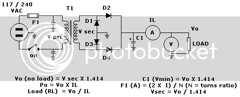
Diode drop for rectifier
D2 & D4 = .7v * 2 or 1.414
calculation to find min ac voltage of seconday tap to drive a 6.3V load. Using diode drop in above calculation 1.414 and place in calculation below.
Vsec = [6.3v + 1.414] /1.414
Vsec = 7.714 / 1.414
Vsec = 5.45 vac , nearly spot on with my existing secondary ac heater tap.
6.3v(target heater voltage) x.025(desired ripple 2.5%) = .158 Vms
Vripple = .158(Vrms) x 2.828 ( peak to peak value or 1.414*2=2.828)
Vripple = .442
Charging pulses on 60hz mains power in my case = 1/(2*60hz)
charging pulses = 1/120 or .008333(t)
C1 lets calculate the filter capacitor for this power supply running 6.3 vdc at 3 amps by plugging in the correct numbers into equation below.
C1 (uF) = [ ( IL * t ) / Vrip ] X 1000000(10 to power of 6)
C1 = [ ( 3 X 0.00833 ) / 0.442 ] x 1000000
C1 = [.025/.442] x 1000000
C1= .0525 x 1000000
C1 = 52,500 uf (in this case min 16 voltage rating since its seeing only 6.3vdc)


![Soldering Iron Kit, 120W LED Digital Advanced Solder Iron Soldering Gun kit, 110V Welding Tools, Smart Temperature Control [356℉-932℉], Extra 5pcs Tips, Auto Sleep, Temp Calibration, Orange](https://m.media-amazon.com/images/I/51sFKu9SdeL._SL500_.jpg)


