You are using an out of date browser. It may not display this or other websites correctly.
You should upgrade or use an alternative browser.
You should upgrade or use an alternative browser.
Beesneez BV-08L wiring
- Thread starter doqmemory
- Start date
Help Support GroupDIY Audio Forum:
This site may earn a commission from merchant affiliate
links, including eBay, Amazon, and others.
mhelin
Well-known member
Btw. BV08 primaries and secondaries are usually connected in series on both sides (not with each other) or secodaries in parallel in some cases but isn't it possible also to connect the primaries in parallel? That would make the transformer into about 3:1 one, is that ok, what would happen to the primary inductance (number of turns remains the same)?
I am building a Phaedrus SPIRIT phantom-powered U47-style mic with this transformer.Btw. BV08 primaries and secondaries are usually connected in series on both sides (not with each other) or secodaries in parallel in some cases but isn't it possible also to connect the primaries in parallel? That would make the transformer into about 3:1 one, is that ok, what would happen to the primary inductance (number of turns remains the same)?
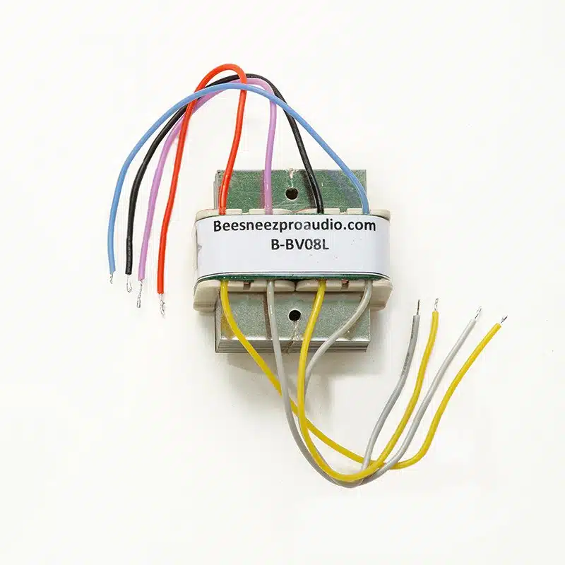
My guess is that red and black are p+ and p-, resp., with
(Edited with correct colors)
Measuring the winding resistances should at least give a clue?
I was hoping that someone already had the diagram. I contacted BeesNeez about it last week, but still have no reply. I have failed to find any information on the BeesNeez website, GroupDIY, or Google. My next step is to measure continuity and resistance to validate my hypothesis, as @Khron suggested, but knowing the actual wiring would make me more confident.
Last edited:
Each half of the primary should / will have a notably higher resistance than each half of the secondary.
Regarding the phasing, even if you happen to connect the primaries and/or secondaries "in the wrong direction", you won't damage anything, you just won't get any audio signal, and you'll be at worst two reconnections away from getting it right.
This would've been a 10-15min job if you reeeeeeeally took your time. But hey, if waiting for days to get information you may or may not receive is how you get your kicks...
innercityman
Well-known member
I made an U47 with this transformer. Grey and Yellow are connected together. I used Moby's diagram as a reference. Here's a pic of my build. And check Moby's page...Anyone know the wiring diagram for BeesNeez BV-08L ?
https://www.mobytransformers.com/_files/ugd/692932_25ea5f4fa2a440f3aad6ccb6bcf96389.pdf
Attachments
Thanks, I was also using Moby's Bv-08 as reference, since I used it with my D-EF47.I used Moby's diagram as a reference.
It seems like such an obvious thing to have schematics. I am building it like the AMI U47, with the resistors on two little boards surrounding the transformer, so I want the wiring correct the first time.
innercityman
Well-known member
Don't expect to get any answer from Beesneez. I wrote them few times without any answer.Thanks, I was also using Moby's Bv-08 as reference, since I used it with my D-EF47.
It seems like such an obvious thing to have schematics. I am building it like the AMI U47, with the resistors on two little boards surrounding the transformer, so I want the wiring correct the first time.
By measuring resistance, I found the following (corrected in the earlier post):
| Primary + | red |
| Primary - | black |
| Secondary + | pink |
| Secondary - | blue |
| Primary spools | yellows tied together |
| Secondary spools | whites tied together and center tapped |
- Joined
- Mar 15, 2022
- Messages
- 111
Dang I'm wondering the same about the Beesneez 13:1 and 6.5:1 toroidals as well (and what mics a 6.5:1 is even used in, anyway).
U47what mics a 6.5:1 is even used in, anyway).
Similar threads
- Replies
- 8
- Views
- 532
- Replies
- 7
- Views
- 745
Latest posts
-
-
-
-
[Build] CAPI VP312~500/51x Series~Preamp Kit~Official Support Thread
- Latest: REDtone Studio
-
-


