Behringerj C-1 Microphone Repair

GroupDIY Audio Forum

Help Support GroupDIY Audio Forum:

This site may earn a commission from merchant affiliate links, including eBay, Amazon, and others.

MicMaven

Well-known member
Joined
Jun 4, 2022
Messages
426
Location
USA
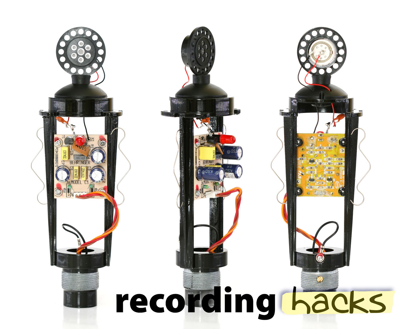
I must repair a Behringer C-1 microphone. A component lead has lifted from the circuit board, and I am unsure to which solder pad it connects. A close-up photo of the bottom (unprinted side) of the circuit board showing where and how the red mic element lead is soldered would be hugely appreciated. This is at the top end of the circuit board - the edge closest to the mic element.

Absent a photo, a clear description of where the red wire is soldered to the board would be hugely appreciated.

THANK YOU. - JR -
 
Thank you for the link. It appears there are at least two versions of this circuit board. The circuit shown in the linked photos has a top-side FET, while mine has a bottom side SMD transistor (situated where the red circle appears on the linked photo.) I suspect the SMD transistor on my board is bad. The red lead to one of the pads in the red circle, whereas it goes to one lead of the top-side transistor in the photo.

Crazy, eh? THANK YOU for the link. I will continue my search for a photo of the board in my C-1 (although given the number of modifications in the linked article, it may be easier to replace the board with a better one!)

Happy trails to you. Thanks again.

Does anyone have a photo of my second-type circuit board? JR
 
if you google "Behringer C-1 inside" or "Behringer C-1 pcb "you will find different photos of different pcb revisions

behringer-c1-pcb.jpg
 
Thank you for the suggested search string. I have tried every combination I can think of, and very few images of the circuit board in my example have appeared. While the images attached to your post are fairly detailed, they depict a slightly different circuit board - the one with a top-side FET. My circuit board is different and lacks the FET shown in the recording hacks images.

If I cannot repair it, I will strip it and replace both board and capsule to salvage the body and build something that works. Until then, it is frustrating not knowing where to solder the lead which has lifted from the board during cleaning.

Thank you for the suggestion and assistance. JR
 
Um ... er ... nope. But I will later today !! Thanks for the suggestion - I will try it later (need some sleep having been up all night working on another project...) JR
 
The schematic is readily available online, so even though the pcbs have different revisions maybe the schematic is the same, or at least close enough to help you on the missing connection


no_html,1
 
I am working with the schematic, but I am embarrassed to report I have difficulty translating the schematic diagrams to actual circuit boards. Just not my strongest suit.

I attach a photo of my C-1 board. I added a circle indicating where the part lead lifted from. There are two pads (hard to see in the pic) and neither has solved my problem.

I suspect I may have damaged a very small black surface mount device residing immediately next to point where the lead lifted from. I worry I may have accidentally touched it with my solder iron - as I get older, my hands are not as stead as they once were. I suspect that is why neither of the likely solder pads have worked.

I am grateful for whatever guidance I receive. I purchased the microphone as a donor case for a home-brew mic build, but I would like to test and compare my build with the original - seems a waste I cannot get it to work.

Thank you for looking over my shoulder.
Happy trails to all. JR
 

Attachments

  • C_1 Circuit Board solder issue IMG_0673.JPG
    C_1 Circuit Board solder issue IMG_0673.JPG
    164.8 KB · Views: 24
  • C_1 Circuit Board Solder Question.jpg
    C_1 Circuit Board Solder Question.jpg
    154.8 KB · Views: 25
Its looks ,as far as I can tell the repair you made is good , the red wire should connect to one side of the brown cap , the other wire on the cap goes to the solder pad on the board . do you have phantom power engaged ? this mic need 48 volts to work .
 
I added a circle indicating where the part lead lifted from

If you look at the photos attached by Whoops in an earlier post you can see that these mics have the capsule wire connecting to a cap that only has one lead connected to the circuit board. That node needs low leakage current, and the typical (more robust) way to do that would be teflon insulated contact posts installed on the circuit board. That will eliminate any chances of the capacitor lead breaking if you drop the mic, but costs several cents more, which Behringer will not tolerate. ;)

Are you sure the mic is broken? If so perhaps you are fixating on the wrong thing, since that cap connection looks just like the pictures of working devices attached above.
 
To Tubetec: I agree with your assessment and, yes, I tested it on a mixer and and two pre-amps, each providing phantom power.

To ccaudle: I follow your train of thought. I suspect I may have damaged the component that shares the solder pads of interest, perhaps with heat from my solder station. Unfortunately, I purchased it used, and tried cleaning it before testing it, so it may have arrived broken.

Thanks for the replies. I appreciate having you look over my shoulder.

PS - Parenthetically, I am a ham radio operator and I have designed and built several electrical circuits for matching various microphones to transceivers, but this little peccadillo may lie beyond my current skill set to troubleshoot, It sure has me up a tree! JR
 

Latest posts

Back
Top