Bipolar Opamp in Hi-Z input circuit

GroupDIY Audio Forum

Help Support GroupDIY Audio Forum:

This site may earn a commission from merchant affiliate links, including eBay, Amazon, and others.

Mondy

Well-known member
Joined
Feb 11, 2012
Messages
59
Location
UK
Hi

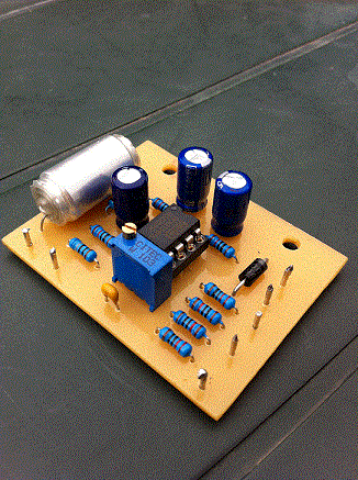
I knocked up a small preamp for amplifying a magnetic pickup in my acoustic guitar, and have been gigging it with great joy for a few years and have always been very pleased with its sound. The circuit is basic and uses an OPA2134 as a gain stage and phase reverser, and is as below

Pre_Schem.JPG


The other day, I tried plugging in an LM4562 in place of the BB chip and was amazed at the improvement in the sound clarity and detail, the guitar sounds much better through it both in phones and my PA setup. But I am wondering if the LM4562, being a bipolar chip, could give me problems as the input impedance needs to be 1 MEG and is better suited to FET varieties of opamp. The PCB is quite small and as you see from the schem there is no supply decoupling directly on the chip supply pins. The OPA2134 behaves itself nicely, but then it is quite a forgiving chip!

Do you think the combination of chip and circuit could cause problems, other than the increased quiescent current, such as DC offsets etc, and are there any simple checks I can make to see if the LM4562 chip is behaving itself or not?

Thanking you all!

Ray
 
Seems surprising that the difference is so noticeable.

Here is two ideas.

1) There may be a filter change.

Not sure, but I think you can view the 30K input impedance plus the 10K R2 (40K) as being in parallel (or maybe it is in parallel only to the extent of the input current of the amp? You need someone smarter) with the 1Meg resistor.

By itself the 1 meg R1 and the 47nf combo makes a high pass filter down 3db at 3 Hz, and dropping 6db per octave below that.  You couldn't hear it.

But might the 30K differential impedance on the new amp plus the 10K R2 be viewed as "in parallel" with R1 (it is not a virtual earth amp, so not sure if this is right... ).  So instead of 1Meg you could have 38K isn.... Which with the 47nf cap gets you a High pass filter down 3db at 90hz, and you could hear that on a guitar.

Maybe you like the low cut? 

You could test this by changing C1 to about 1uf, which would put the corner in the same place as it used to be.

2) Another idea, What are you plugging this into?  If it is something with a substantial load like a mic pre rather than a line input, there could be a difference in what the load is the amps can drive.

...
 
Hi Bruce

Thanks for your reply, which would make a lot of sense!

I admit I was too quite surprised at the difference it made to the sound as the OPA part is certainly “Hi Fi” enough for the app, but your impedance change point could explain it nicely. I always thought the non-inverting input would be set by the value of R1 in the circuit and then present a 1MEG ohm load to the pickup, I did not know I would be different for various opamp topologies. It serves me right for designing by Google!!

Incidentally the output of each amp is directed via a switch to a 10uF output cap into a 10K volume pot on the pre, depending on what phase is selected, and then off to whatever I plug into (generally a mixer input with 20K or greater Z or an active DI)

The change in sound aside, do you think there would any problems with using the LM part in this circuit as it stands as I would rather have the OPA part functioning well than an opamp that sounds good, but could be unpredictable, as this I my main gigging pre for my guitar?

Cheers
Ray
 
It's a guitar..... if it sounds better, go with it.

The input noise current is higher than bifet and will dominate the input noise, but in the context of a couple volt guitar pickup will not be all that bad. I wouldn't use an old school bipolar opamp but new improved, why not?


JR

PS; I don't see what that 10k in series with + input is doing besides adding noise.
 
JohnRoberts said:
PS; I don't see what that 10k in series with + input is doing besides adding noise.
It´s a relic of the 70´s.  Some thought it would protect the chip from damaging.  With FET-opamps it would make sense - but only together with protection diodes to V+ and V-.  The TL072´s in the Marshall Valvestate were typical victims cause they didn´t have the diodes.  The TL072´s were damaged by static discharge or so by plugging the instrument in.  Afterwards the Amps became noisy.  Noisy Marshall Valvestate = damaged TL072 input stage.

A funny side-story:
there have been the AM7910/7911 modem-chips.  Very good chips, they even had protection-diodes at the input. Now these comfortable chips were used for radio-data-transmission.  They were put in a box on a mountain, and every several weeks the chips had to be replaced.  What has happened ?  After analyzing several of those broken chips, the reason was found: the protection-diodes.  Normally the voltage at the input should be at 0V.  The damaged chip were hanging either at +5V or -5V - depending on which protection diode was destroyed by the last nearby lightning stroke.  Additional external protection diodes and a series resistor solved the problem.

analogguru
 
Thanks for your replies!

Analogguru is right, I thought it would add “some” degree of protection to the input of the chip as the OPA2134 was a FET device. I can see now as JR reckons, without the diodes to the supply lines, it probably is just sitting there raising the noise floor. It is a preamp for live work however and the circuit is more than quiet enough for this purpose. 
Anything you guys can recommend to improve the circuit for either the LM4562 or the original BB chip would be appreciated however, particularly in the area of input RF and static/voltage protection or anything else you pro's would change etc

Cheers
Ray
 
Modern ICs are more robust about input pin protection. Significant silicon area is dedicated to this internal protection.

I recall from reviewing service history (years ago), most product failures occur to ICs directly interfacing with the outside world (input/output jacks). No doubt due to static, but in live sound the occasional hot ground can kill stuff too. 

JR
 
Mondy said:
...nything you guys can recommend to improve the circuit for either the LM4562 or the original BB chip would be appreciated however...

Well I think you should start by figuring out where you like a low cut filter to be set.  Because clearly you like that sound better.

But one thought, a low shelf can sound a lot better than a low cut (which is what you have created).  So you might want to experiment with the old chip and using an EQ and figure out what response curve sounds best on your guitar.

I think if you knew that, you could make either op amp sound the same, and possibly better because you could have better control (the filter you built is a simple cutoff, but maybe you really don't want it down 9 db at 45hz (that's an octave lower than your 3db point... Maybe a shelf would be nicer... or maybe you want the cut to start lower.

If the sound you like is really an EQ change, then you are much better off doing it in EQ.  (the DI box could be flat and flexible, that cut would not be good on a cello... or upright base.)
 
Hi Bruce
Thanks for your help!

Your first reply got me thinking as to what I was actually hearing and so I ran the preamp through a frequency response check using ARTA. It showed a nice flat response with the low end to be 3db down at 24.6Hz. I measured R3 and it was 669R and C5 a smidge over 9uF so it looks like the low end is being rolled off correctly via this pole as I had planned (I designed to cut around 25-30Hz).  If the input components had formed this pole then 24.6Hz would suggest an input impedance of around 138Kohm and I can’t see how that could be (the 47n is a 1% polystyrene). I didn’t short out C5 and retest to find out for sure, as it would mean taking the preamp apart, so I just assume that the input impedance is being set by R1 (hopefully as I need 1MEG here!)

My thinking is that anything below about 60Hz is generally what you try to get rid of with an acoustic guitar (not using it for Bass) and most of the time I run through an 80Hz High Pass on my channel input as this cuts down handling thumps and general low frequency nonsense. I always run flat to the mixer and apply any EQ on this rather than any battery or phantom powered EQ, that is why the preamp is a just a basic gain stage.  So I should be getting all the bandwidth I need, but there seems definitely more detail and clarity with the LM4562 part over the OPA2134 when run flat.

I am still not sure if I like the idea of not knowing if the LM chip is happy in this circuit or not, as you don’t get second chances during a performance! So I am still in two minds. I may even try making a new board with some 10nF or 100nF caps on the chip supply pins and then I would feel happier sticking with the LM4562. The board is quite small however and so I am hoping it could be OK as the supply traces etc are quite short and close to the large supply caps

Pre_Board.gif


Can you recommend any tests that I can do to check if the LM part is happy in the current circuit? I have an AF sig gen and an old scope if these can be out to good use.

Cheers
Ray

 
Well clearly my understanding of the input impedance was flawed (I.E. completely wrong).

I don't understand the big difference in sound you are getting.
 
bruce0 said:
I don't understand the big difference in sound you are getting.
If you don't understand why you are getting good sound, DON'T CHANGE ANYTHING until you can make another one that sounds the same.

Then you can fiddle with "improvements".  Otherwise, you may lose the magic forever.
 
> I don't see what that 10k in series with + input is doing besides adding noise.

It is fairly customary to throw 34K in series with the first grid of a geetar amp. Main reason is that 34K against the 100pFd of a grid rolls-off above 50KHz.... the local radio station, taxi-radio, etc. The noise resistance of a guitar pickup is few-K in bass and 50K-250K at the treble resonance. Ear hears that treble resonance, so another 34K is hardly-any hiss. It does no harm, and occasionally saves your butt (not playing duets with WKRP, or rapping with Yellow Taxi).

10K into a JFET amp is hardly-any radio rejection, I'd add 100pFd back to jack ground.

The chips are diode-clamped, but what is the current? Is there any internal resistance? Assuming 10 ohms bond resistance and a signal spike 1V over the rail you could have 100mA! Assuming the clamps can pass 10mA safely, 10K added allows inputs to 100V safely. If you have more than that on anything that resembles a 1/4" plug, you have problems.

I would poke the chip outputs for DC voltage. You don't have output blocking caps. Many inputs do have caps, some don't. A "low noise" BJT input fed through 1Meg could induce a half-volt of offset. Your amp has DC gain of + and - 1. So you could have +0.5V and -0.5V DC going into the next box. It would be better if more like 0.01V (10mV) though most stage-gear should eat tenth-volt harmlessly.

I wonder if any of your "change of sound" is the specific next-box you are going into? If it is not DC-protected it may be offsetting itself to a point near musically-euphonious overload.
 
Thanks PRR.  I was baffled for a reason.

The idea of overloading the next stage makes sense to me. 

So if the offset is the problem then a blocking cap on output would make the guitar sound the same on both chips.

PRR:
I don't know if the answer to this question is too big or off-topic for this thread, but can you tell me is there some reason this offset develops more on BJT than a JFET input (because the current to the input is higher?)?  Why are low noise BJT's more susceptible to that offset?


Input current of a JFET is nearly zero.

Input current of a BJT is significant.

Input current of a low-current general-purpose BJT may be 0.1uA.

Input current of a low voltage noise BJT may be 10uA to 500uA.

500uA in 1Meg is 0.5V.

BUT: look at LM4562 specs. Input 10nA typ 72nA max. Or 0.010uA-0.072uA. This is quite small even in 1Meg.
 
Input bias current.  Got it. Thanks, very clear.


So even at 73nA max input bias current, that should get about 36mv on the outputs.

 
PRR

Many thanks for your very excellent practical analysis and advice, much appreciated! The circuit shown does feed an off board 10uF blocking cap (with + facing the opamp) and then on to a 10K pot for volume. This is not shown in the schematic and sorry if this was misleading.  I will check pre this capacitor and see how the DC offset is looking. 

Bruce, DC offset for the LM4562 in this config looks like to be anywhere from 245mV to a little over 1.6V, depending on the chip tolerances. PRRs assumption would be probably more real world, you can check it here…

http://tangentsoft.net/audio/calc.html#offset

I put a scope on the output and ran some square waves into it and the resulting traces look pretty good, very slightly sloping tops and bottoms @1khz, but I guess this could be down to the LF roll off,  it gets better as the frequency is increased. The leading and trailing edges look good and fast with no signs of any ringing or drastic overshoot. With sine the wave is good and clips nice and symmetrically and goes into and comes out of clipping at the same point. Couldn’t find any HF oscillations further up the dial and the input current is a steady 9.9mA in all conditions and so it looks to be behaving itself

I will check the DC offsets either side of the DC blocking cap tonight and report back

Once again, thanks both!

Ray


Hi

I checked the DC offset for the circuit with both chips. From AGND to both amp output pins direct it read 0.021V with the LM4562 and practically nothing for the OPA2134 with both quiescent and signal in conditions (as this seemed to be 10x less than predicted by the calculator link, I checked this with two multimeters and they both agreed). As I use the input jack to switch on the preamp stomp box style, hence the need for an output coupling cap, the output referenced to the battery 0V was half supply voltage + 21mV as expected. DC offset on the other side of the output cap to 0V was too low to measure. So all in all, it looks like the LM4562 is in there to stay and I will just have to charge my battery a smidge more often!

Ray
 
> 10x less than predicted

There's two numbers for input bias: MAX and so-called "Typical".

Typical is often 10 times lower. Typical is NOT guaranteed.

If you (correctly) computed on MAX, it is not unusual to find 90+% of your production running close to 10X better than MAX predicted. But if you make/use enough, you are sure to find a few 2X typical, and you can not complain if you find some all the way at MAX.

(Actually, even MAX is not certain, testing is statistical sampling and tweaking to keep the process away from the limits. But if you get more than a few over MAX, and you are a *big* customer, the maker may try to make-good with a few freebies and a memo to the fab.)
 

Latest posts

Back
Top