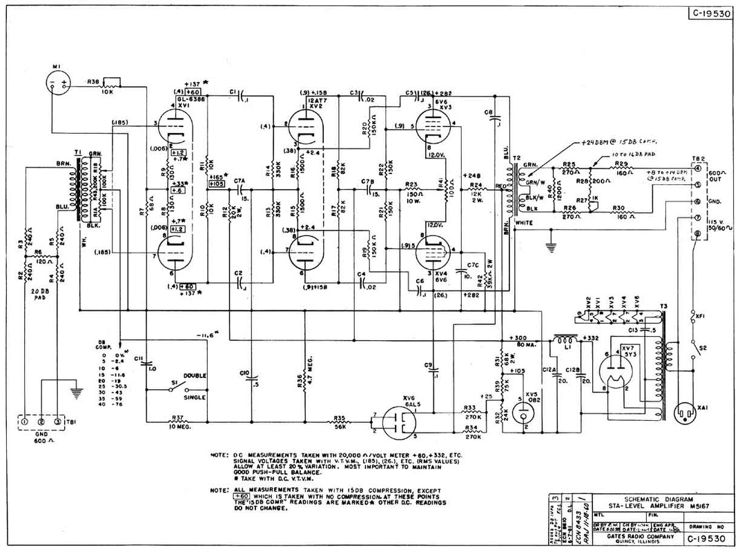
Hey guys, I have built a 24 position 600 ohm bridged t for the output of a Gates STA build. I finally got it all up and running yesterday but noticed one of the 600 ohm series resistors on the attenuator had burnt out. I replace it and measured the voltage across it and when I'm attenuating quite a bit, or driving the input pretty high, the resistor is heating up a lot and I'm sure if I push it further again it will just burn out. There's about 65-70V across it so it makes sense that it would be getting so hot as I'm only using a 1/2W resistor, but even a 2W would burn out with that voltage. I copied my design from Friesdan's, just changing the attenuation values to suit my needs.
I can have the attenuator pulling the signal down about 46dB and it will do that fine, but if I drive the signal in a little harder with the input it will start to burn that resistor. I'm using the Hammond 1650G on the output. I don't know if I'm missing something simple here, or if I've wired it incorrectly so that it's drawing way too much through that resistor, but I also can't imagine using 2 huge series resistors in place of the 1/2W or 2W.
Here's a link to the drawing that I followed for my design: https://www.dropbox.com/s/gvilt1th1ofvu83/bridged%20t%20600%20ohm.jpg?dl=0
The issue it's the series resistor connected to the input of the attenuator the burns up. I'm using Drip's pcb for the build, and I have the "to attenuator" as my IN, "from attenuator" as my OUT, and COM connected to the pole of the 2nd deck. I've also connected COM to ground as my signal was noisy without doing this. It was a bit unclear to me as to whether it needed that but it was the only way I could get a clean output signal on my scope.
Any help is hugely appreciated!
George
")