glazer56
Well-known member
Greetings!
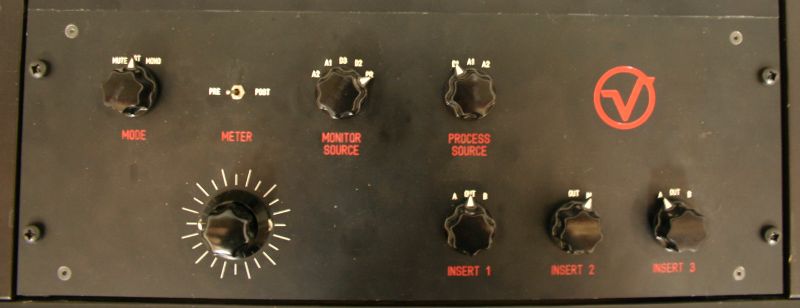
I am currently adding a dedicated mastering room to my recording studio, and will need to build some sort of mastering console to control all the DIY gear that I have built, and am building ;D I have learned quite a lot from this forum, and hopefully I can give back a little by offering up some schematics for review, and possibly offering a group buy on PC boards if there is any interest. I certainly don't claim to be an expert designer, though I've completed many successful projects, including some custom preamps and EQ's. So please excuse the schematics if they are a little hard to follow!
My goal for this build is to create a passive relay based mastering console to switch in and out various hardware units, as well as to enable a M/S encoder/decoder. In addition, I am adding a full monitoring section, with a separate attenuator, L&R Mutes, polarity reversal, L/R swap, mono and a bypass. I am thinking of adding an attenuator before and after the inserts, though these can be easily bypassed. All the switches and attenuators would be connected to the PC board via terminal blocks, allowing virtually any type of switch to be used, or to allow certain features to be bypassed if you so choose. Since there will be quite a few i/o points, I was planning on using these dual TRS jacks to save real-estate:
http://www.mouser.com/ProductDetail/Amphenol-Audio/ACJS-MHD/?qs=sGAEpiMZZMvlX3nhDDO4AIjVaYpuavU1dYROEEZH59E%3d
The main inputs would be panel mount XLR's, (or your connector of choice) which would be hardwired to the input selector switch and the input attenuator before the signal hit's the PC Board. The monitor attenuator i/o's would also be panel mounted, since these could simply be hard-wired in, saving PC Board space and saving on manufacturing costs. Rather than reinvent the wheel, I plan to use a JLM power supply, though you could use any power supply you wish, as it only needs to supply power to the relays, and possible switch LED's
Here is the initial schematic, any suggestions, comments, critiques and criticisms welcome! thanks! ;D ;D ;D


![Electronics Soldering Iron Kit, [Upgraded] Soldering Iron 110V 90W LCD Digital Portable Soldering Kit 180-480℃(356-896℉), Welding Tool with ON/OFF Switch, Auto-sleep, Thermostatic Design](https://m.media-amazon.com/images/I/41gRDnlyfJS._SL500_.jpg)


