CAD M177 MIC MOD

GroupDIY Audio Forum

Help Support GroupDIY Audio Forum:

This site may earn a commission from merchant affiliate links, including eBay, Amazon, and others.

murt

Member
Joined
Aug 25, 2004
Messages
8
Location
Dallas, TX
Hey Fellas,

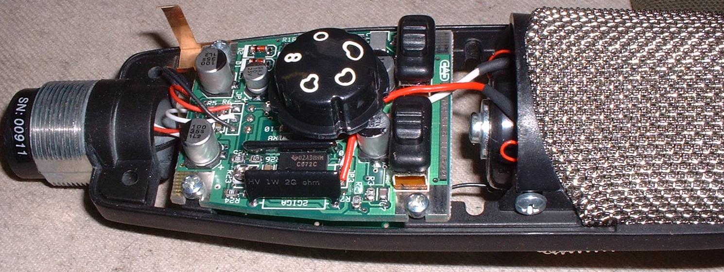
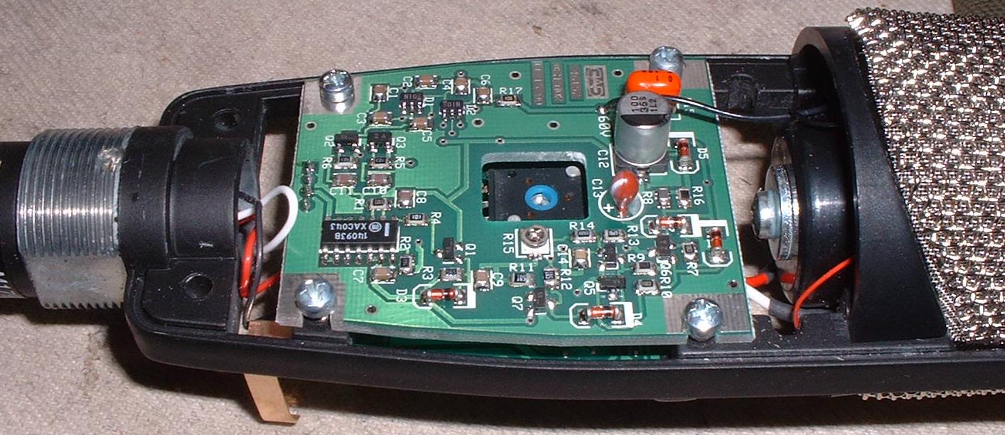
I've got this crazy notion to modify a CAD m177 Condenser mic. I'm still quite the newbie here so please bear with me. What I am thinking of doing is replacing the TL072 OpAmp with an OPA2134 or OPA2604 or some other fancy variant. I'm gonna put in a dip socket so I can change out the IC's to see which on if any make an improvement. Also there are some Tantalums in the Low Cut section I'm thinking of replaceing with Poly's. The Tantalums are 35V. My question is as follows, Can I use a higher voltage poly in place of the tantalums, and how is the polarity effected? The board has + sign on one side of the Tantalum. Also, there is somee kind of issue with some of the bigger Aluminum caps that causes a squeaky cherp every 10-15 seconds,
Any recommendations on a good replacement for these (100uF 35V surface mounts).

Thanks for any help you may provide...

Murt
 
I'm definitely curious about possible mods, since I've got a M179 and it's a bit bright for my taste.

The op-amp choice is going to be limited by power consumption, since the mic is phantom powered. Check out the spec sheets and make sure you're putting in something which draws about the same power.

With film caps you can just use higher voltage ratings without compromise - they don't have the biasing requirements of electrolytics or tantalums. Physical size is the main limitation. I haven't opened up my M179 yet.
 
Cad Mic Update

I will post pictures as soon as I can!

I ordered Parts from DigiKey today. TI and Analog Devices were both kind enough to send me some sample IC's for free.. So here is what I have coming to try out in this mic.

From TI (Burr-Brown) I have OPA2134 and OPA2604.
From Analog Devices I have OP275, AD746 and AD712

Any other suggestions are welcome please remeber that this is running off phanotm power so the current draw needs to be as small as possible.

OK enough with the update.

Here are my newbie questions again...

Is there any reason to replace the tantalums? I seem to have the impression that they are not the best, Am I right?
If so where do you find a Poly or Film Cap in a 10uF with a 3-4mm lead spacing?

Thanks again for all the help Gang..
I'll keep you posted..
 
I'm confused too, TK.

I have a M37, which is supposed to use the same capsule and OAs as the M177. Mine has the same as yours, I believe, though I don't have it here at the moment to check again.

This mic is a little brighter than some other mics I have and if the singer is silibant, it *won't* work. But I love it as a drum OH mic. I have used it on some singers that are not so silibant and it works great, not for everyone.

I think that Gus will be along to say that replacing the SMT electros is a good idea. I'll say I would advise against replacing the OAs.

Good luck soldering a DIP socket in place of the SO-8 ICs, unless yours has DIPs, the M37 is SMT. The tants are probably bypass caps and would not be in the audio path, though I can't confirm at the moment.

**EDIT: the Tants are in the signal path as the HP filter! Yuk! and the opamp is through-hole...my mistake... Sorry!

Be careful with AD746 as it is not stable with gain less than 2...check the schemo. The 746 is one fast dude. I like it for I/V conversion in DAC apps. AD746 and 712 are probably going to have more noise than the OPA2107 (if that is what is present in your mic). If you actually have TL072, I would recommend the 2107 since that is what CAD originally used. OPA2604 is more than 2x the idle current of the 2107, OPA2134 is exactly 2x the current of the 2107.

HTH!
Charlie
 
Oh oh!! Gotta correct myself here as I got my mic back home and opened it up... I have spoken too soon!

The dual opamp is thru-hole, though most of the PCB is SMT. The chip used in mine is marked C072, which would be a TLC072, i think. I thought maybe this was a CMOS version of the OA, but it is actually a high-current out version (~55mA)! Check it. Less than 2mA per channel idle current, though it a single suppl amp with a max supply of 17V. I am still not convinced that changing the OA will give you anything though.

I would look at the schem and see to changing the SMT electro caps if they are in the signal path, though.

HTH!
Charlie
 
Just uploaded the schem for the M37...

http://groupdiy.twin-x.com/displayimage.php?pos=-129

I think the M177 is the same. Note that the schem shows OPA2107 but it is actually a TI TLC072, which is a high current version of this FET opamp.

Internal pics to follow!
 
It looks OK for what it is. I don't think a parts change will make a great difference with the stock circuit. The electros look to be formed.

Remember the Neumann u47 fet uses a opamp type circuit that looks like it might be class AB. The opamps in this microphone are AB. Maybe this CAD microphone on a kick????

Taking out the guts and replacing the circuit might be cool. I should state I do not know anything about the CAD microphones first hand. I have only repaired two old 100s?

I don't know if the capsule in the CAD is worth the effort because I have not tried the one in this thread.
 
Here are pics of the PCB of my M37:

http://groupdiy.twin-x.com/displayimage.php?pos=-131
http://groupdiy.twin-x.com/displayimage.php?pos=-132

After Modding:
http://groupdiy.twin-x.com/displayimage.php?pos=-130

When I tried posting these on Fri, I got error messages, but I just now checked and they are posted... ?

And I am confused as to which cap is 10uF as the schem for the M37 shows cap values of 100uF or 0.47uF for full range or hi pass. After modding mine works as it should. I just formed the leads of a box film cap to fit.

HTH!
Charlie
 
I took a couple guts photos of my M179. I didn't want to dig any further, since I've been told that you have to remove the PCBs to get the capsule out.

M179-front.jpg

M179-rear.jpg
 
Charlie

Did the sound change?

The reason I ask is that formed electros even cheap ones don't always sound bad.

I also noted the use of 35V electros on the schematic. I guess the designer(s) calculated the voltage drop across the phantom resistors.

The power supply section seems to have the most parts. The 100uf at 20V might be something to change, if you use a higher current draw opamp.

The capsule supply part might be of use to the DIYers here. I like the push pull 3904 and 3906 part.

The opamps using different parts of the output stage(because of 180 degree drive) might cancel some of the output stage problems in 72s. Also note the use of 2.4K resistors between the output pins and electros to help make sure the opamp is not loaded down to much.

Maybe the old 5k(I first read about this in 1979 IIRC) or so resistor output to more negative supply to help the pnp side of the output, would make a difference.
 
How I remove SMD electros.

I take a pair of cutters and cut the "can" at the bottom between the Al and plastic parts". You should end up with the plastic part and two legs.

I then heat the two small legs an remove them.

You do this if you don't care to save the SMD electro.
 
Scodiddly, I'm jealous of your digicam... Great pics! You only have to remove the four screws that hold the PCB in place to pull the capsule. After the PCB is loose, you just remove the screws on either side of the windscreen and the capsule will drop down.
I am interested to see the caps underneath the pattern switch knob.

Gus, I have not had a chance to really use the mic since I changed it. I normally use it with the HPF on anyway, so that woul be through the tants. And you are right, 50V caps should be the minimum for safety! I like your method to remove the caps too, but I can usually get them off by heating each pad and slightly tilting the body, alternating sides until the cap comes loose.

Didn't know if you can read my PCB, it actually says M177 on it.

Peace!
Charlie
 
Gus

I finally got a chance to try my M37 again after the mods. I only used it as a drum OH mic and with the HPF on. I would say the diff is not dramatic, but I thought is sounded a bit more "clear" and open on the top. Maybe the tants are a part of the harshness that people have commented about here?

Hopefully I can try it as a vocal mic again soon.

Anyone else have any comments about the sound of their modded M37 or M177? How about your changes, Murt?

HTH!
Charlie
 
back from the dead thread!  ;D anyone ever mod the CAD 179? i hear they are good on toms? i'm thinking about some hyper cardoids's for toms, and this could be the ticket for how inexpensive they are....
 

Latest posts

Back
Top