Carrier Microphone Company model 94 condenser microphone, approximately 1932, based on product announcements in magazines. This would be pretty close to the end of the first generation of American condenser mics, with the RCA ribbons just announced and starting to take over. Made in Inglewood California, primarily for the film industry.
I've had this since about 2000, rebuilt it and tested since 2002. It's been shelved while I looked for the unobtainium Cannon mating connector. I've since learned it's 'extra special unobtainium' and I might as well forget it, so I made a connector recently.
This thing sounds far better than expected. It has a peak in the 4-5K range and much less above that, goes well low enough. Sounds really great as ambient drum kit pickup, the kick drum quality is pretty special (read: the right distortion contribution). I can see cutting some lead vocals with it, some horns and guitars would also be suitable uses.
Unlike reports of the early Western Electric condensers crapping out with high volume, this microphone does not. The amplifier goes into limiting type overload with rock drums 6 feet away, and you can see typical single ended class A flatlining against the power rail side in the waveforms. You can't really hear it as distortion though, so it must be fairly strong 2nd harmonic relative to anything else.
Output level would be on par with low output condensers, or medium/high output dynamics.
Power supply would have been battery originally, four 45V B batteries and 6 volt filament. Today there are arguments about the effect on sound quality with various types of DC supplies feeding direct heated triodes like this, which were never considered for use with AC C PSU's in any high quality installations. I haven't been down that rabbit hole, other than to note that any and all ripple will appear in the audio, since cathode and heater are one in the same. I'm using a modified chinese tube mic PSU at the moment. In one ambient test highest noise peak with gain set for voice use was 180Hz (PSU hum) at -74dBFS, or roughly -56dBm. 60/120Hz are equal, and slightly lower. The highest noise peak above 180 is about -90dBFS, most lower than -95dBFS, baseline above 1.5kHz being about -108dBFS. The PSU can definitely be better than it is, and I've not tried a 6V lamp battery for comparison yet.
This mic was designed for a 200 ohm load. In the early days it would be normal to have a condenser mic panel that might provide power, and also have a 200 ohm ladder attenuator to control level to the program amp or mixing panel. I changed the pattern selector on my PSU to be a load switch, ranging from 230R up to 1K6 in 200R steps, and open. This affects both response and level, and gives some useful tailoring.
No great pics yet, but here are a few.
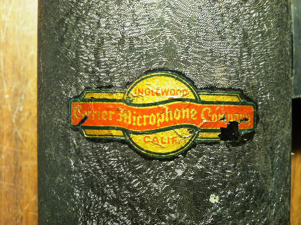
The original water decal was starting to flake off. Most of these I've seen are totally gone. I gave it a localized coating of Polycrylic to preserve what remained.
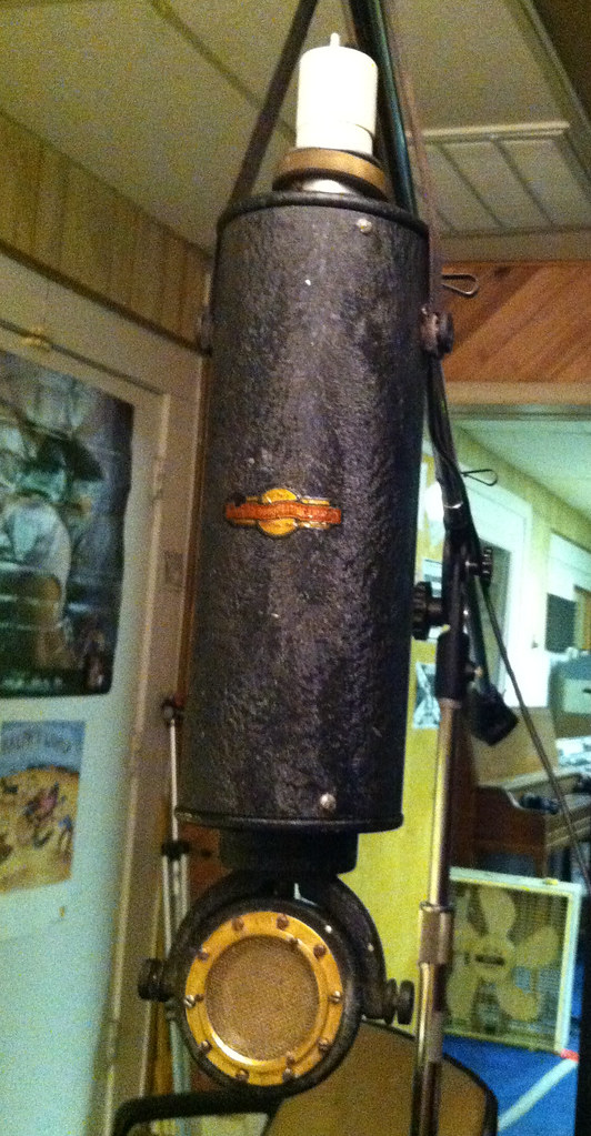
Pics before the recap; on film!
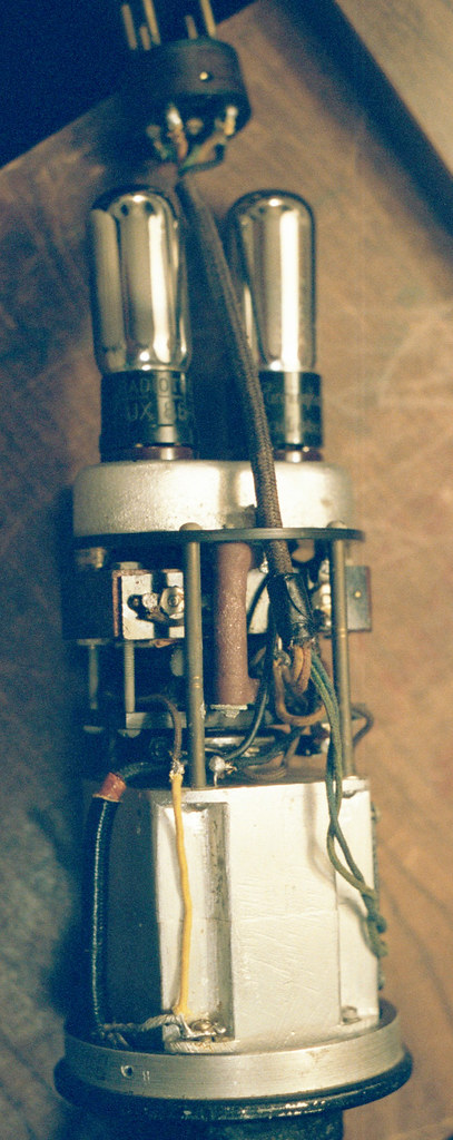
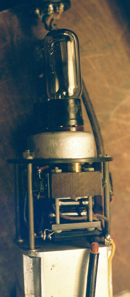
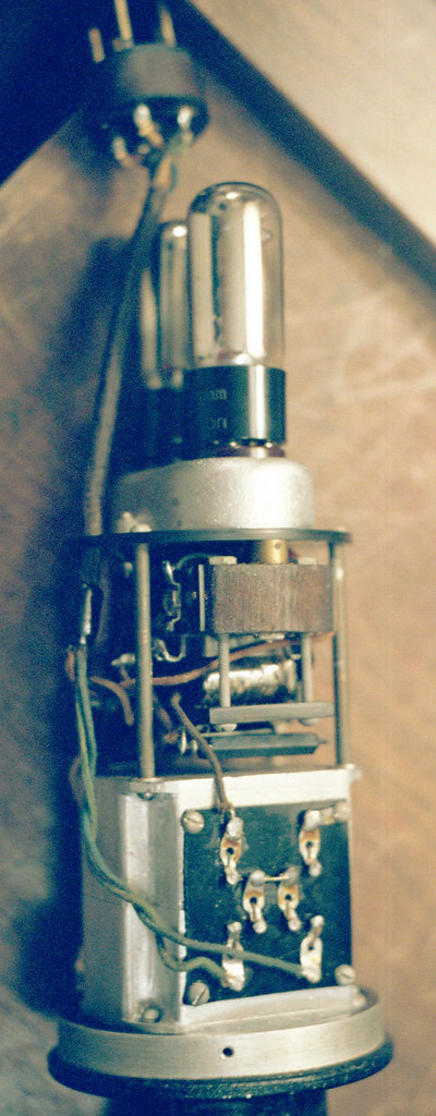
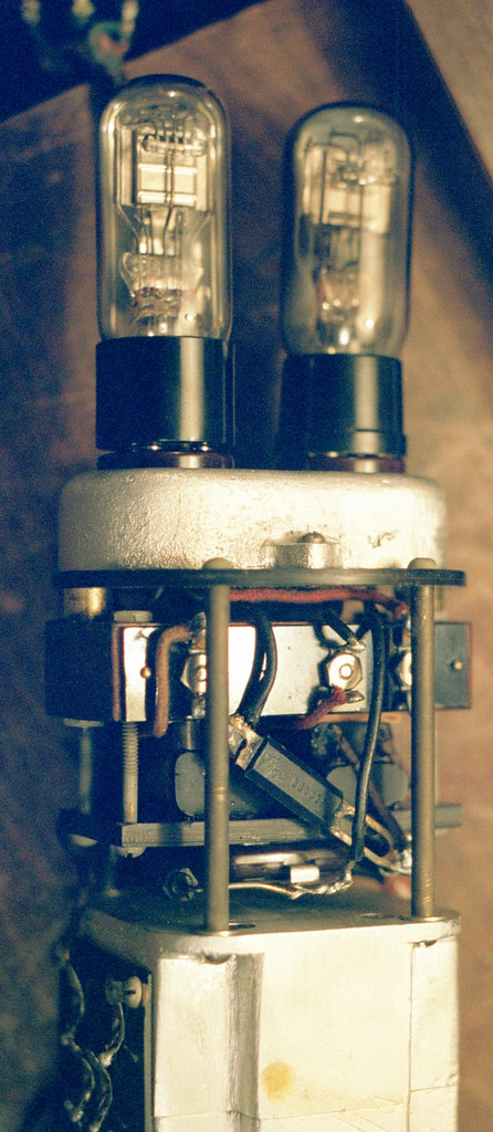
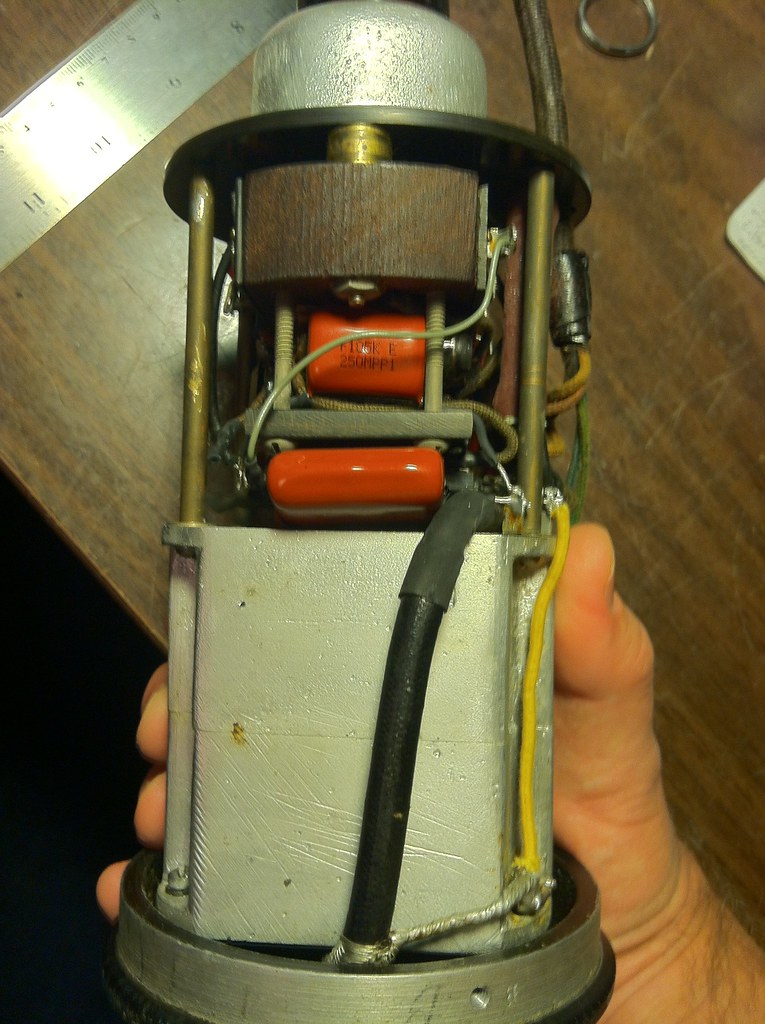
Pics showing the recap. I left all original caps in place, and worked around them, so any anal future collector can return it to original condition if desired.
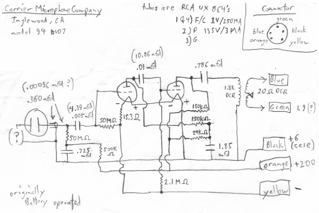
The strangest thing I've ever found when drawing out a circuit was a few of the resistors here; they are mounted inside the block of wood in the middle, which appears to only be terminal connection points at first glance.
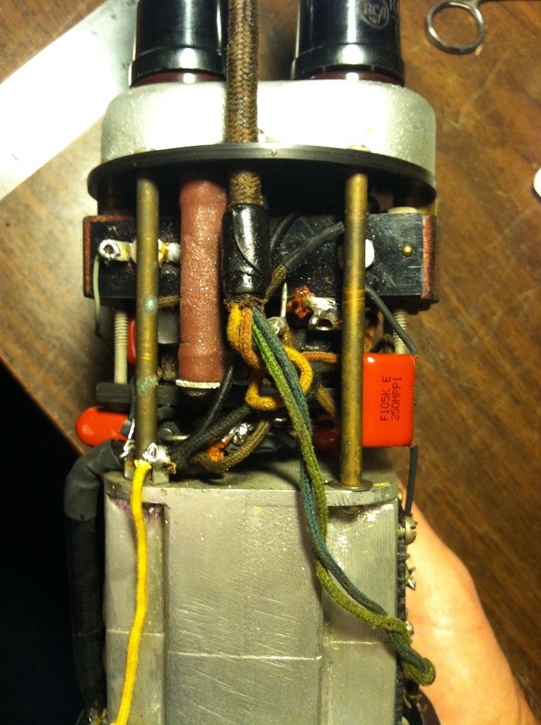
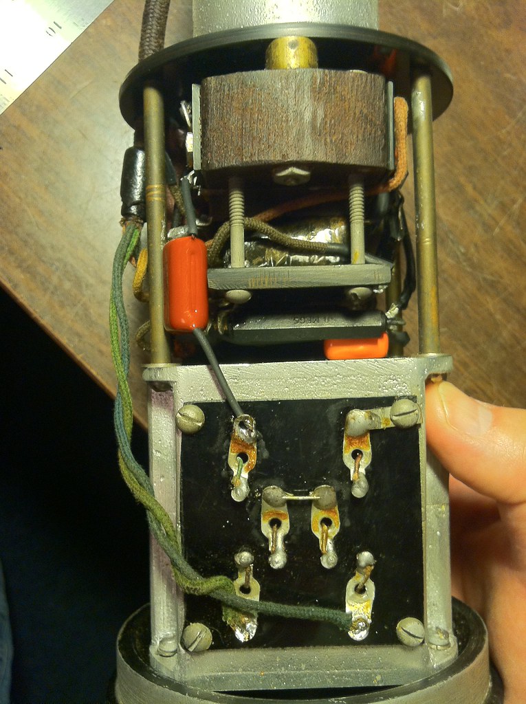
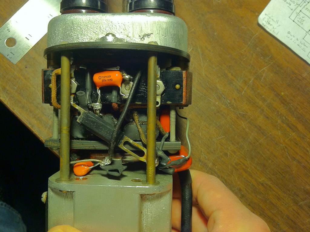
tube sockets
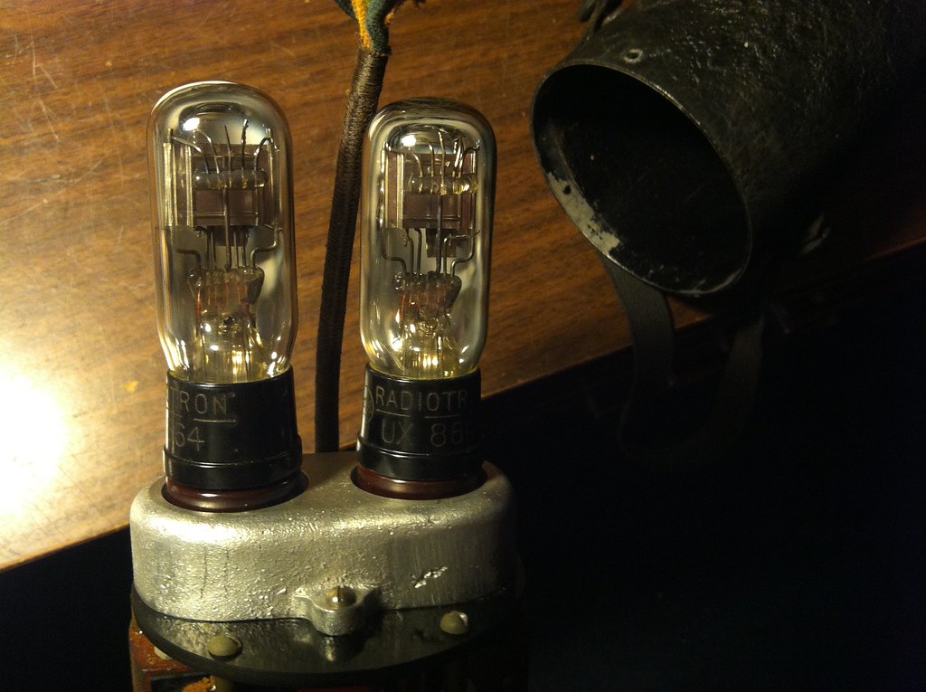
capsule front and back
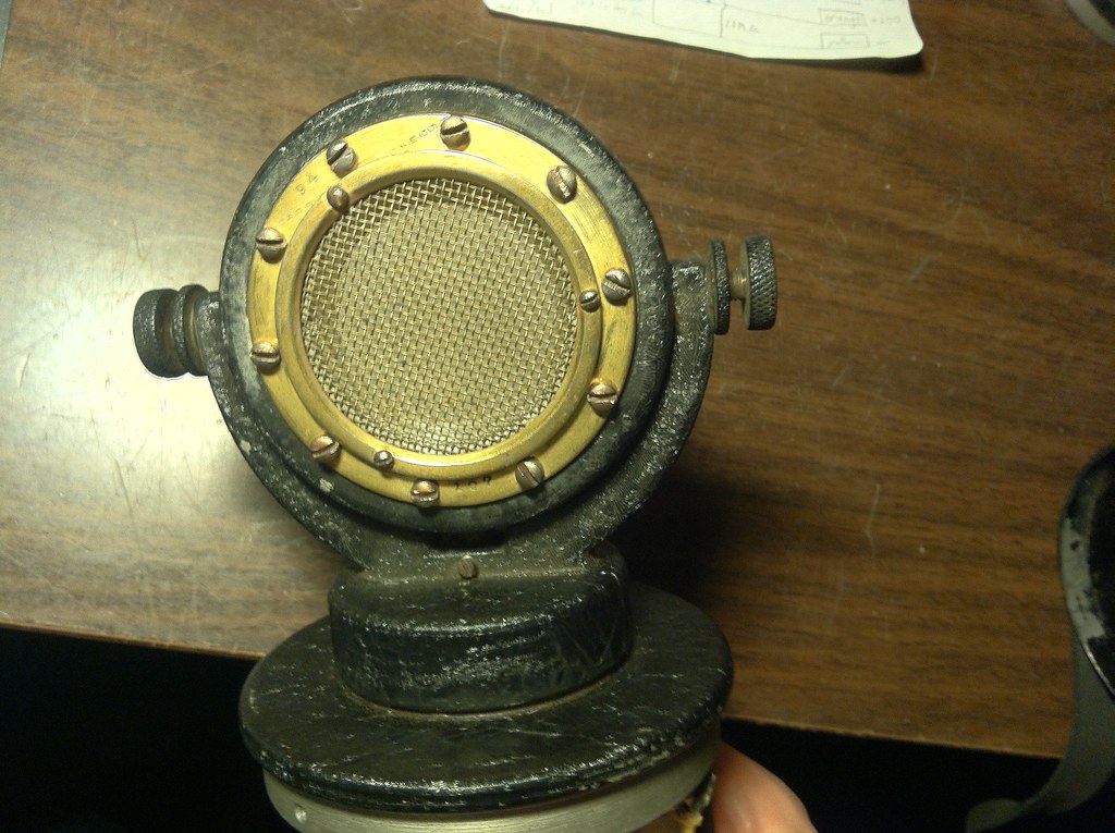
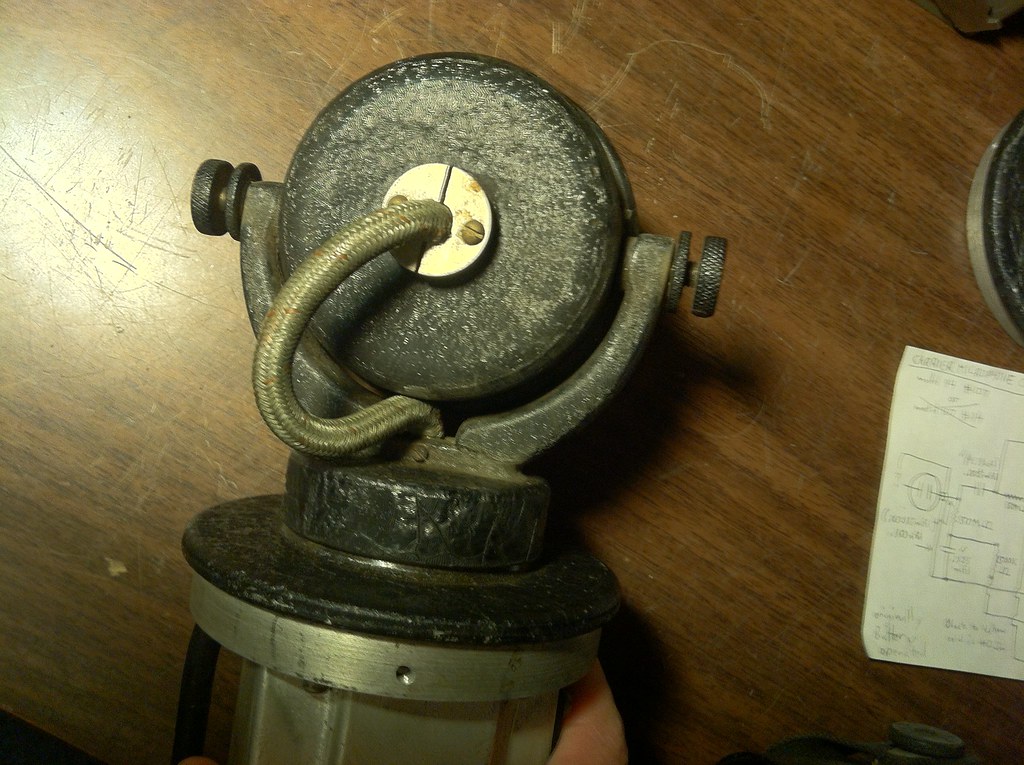
disassembled
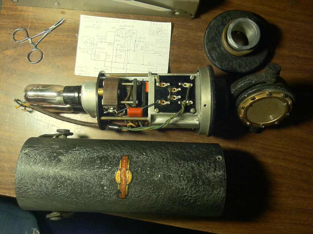
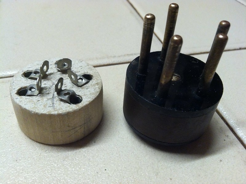
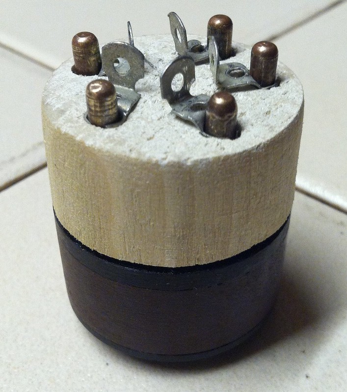
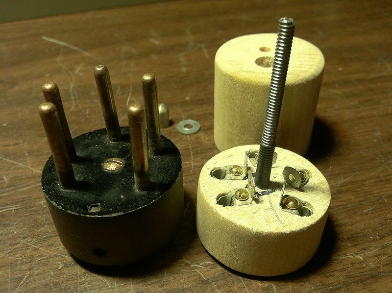
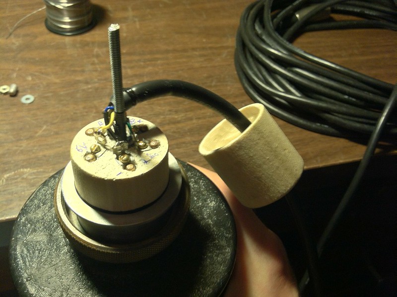
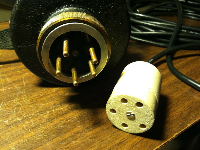
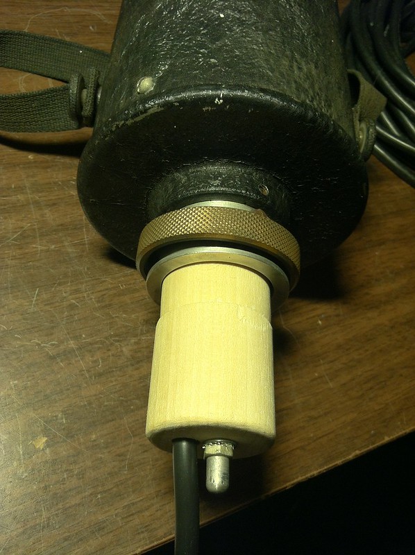
The Cannon connector saga. My home made connector is cut from a 1.5" dowel, pins were robbed from some old stereo speaker press-on connectors, and reshaped. Pin size is 1/8", the same as the filament pins of 4 pin triodes.
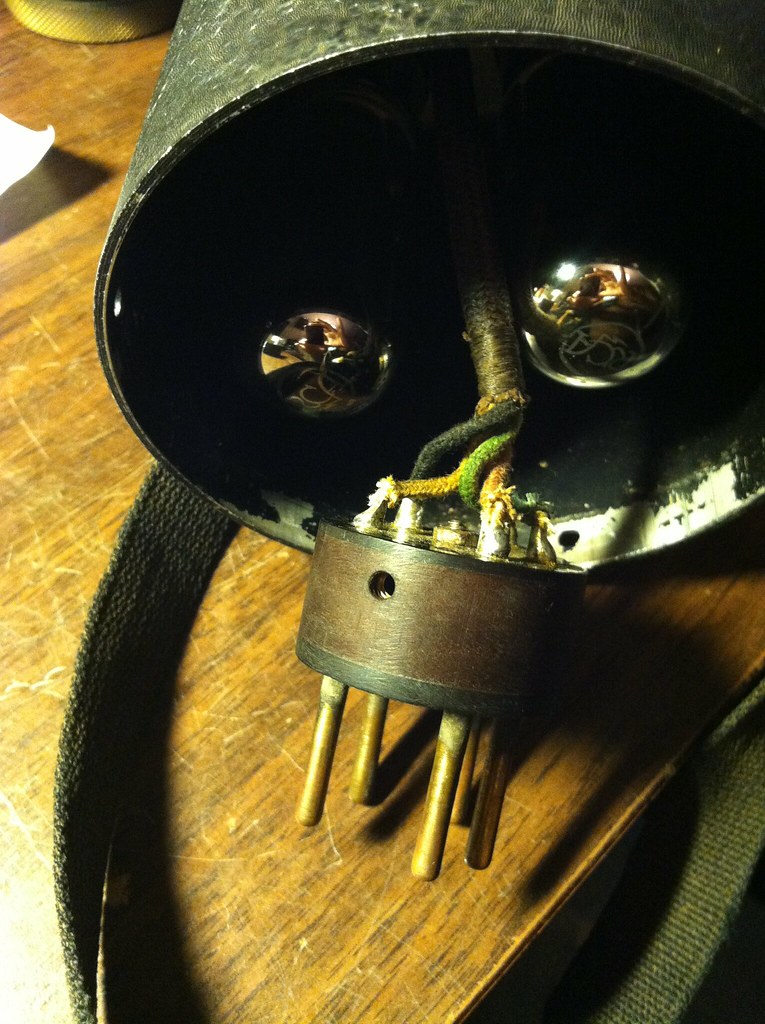
I've had this since about 2000, rebuilt it and tested since 2002. It's been shelved while I looked for the unobtainium Cannon mating connector. I've since learned it's 'extra special unobtainium' and I might as well forget it, so I made a connector recently.
This thing sounds far better than expected. It has a peak in the 4-5K range and much less above that, goes well low enough. Sounds really great as ambient drum kit pickup, the kick drum quality is pretty special (read: the right distortion contribution). I can see cutting some lead vocals with it, some horns and guitars would also be suitable uses.
Unlike reports of the early Western Electric condensers crapping out with high volume, this microphone does not. The amplifier goes into limiting type overload with rock drums 6 feet away, and you can see typical single ended class A flatlining against the power rail side in the waveforms. You can't really hear it as distortion though, so it must be fairly strong 2nd harmonic relative to anything else.
Output level would be on par with low output condensers, or medium/high output dynamics.
Power supply would have been battery originally, four 45V B batteries and 6 volt filament. Today there are arguments about the effect on sound quality with various types of DC supplies feeding direct heated triodes like this, which were never considered for use with AC
This mic was designed for a 200 ohm load. In the early days it would be normal to have a condenser mic panel that might provide power, and also have a 200 ohm ladder attenuator to control level to the program amp or mixing panel. I changed the pattern selector on my PSU to be a load switch, ranging from 230R up to 1K6 in 200R steps, and open. This affects both response and level, and gives some useful tailoring.
No great pics yet, but here are a few.
The original water decal was starting to flake off. Most of these I've seen are totally gone. I gave it a localized coating of Polycrylic to preserve what remained.


Pics before the recap; on film!


Pics showing the recap. I left all original caps in place, and worked around them, so any anal future collector can return it to original condition if desired.
The strangest thing I've ever found when drawing out a circuit was a few of the resistors here; they are mounted inside the block of wood in the middle, which appears to only be terminal connection points at first glance.


tube sockets

capsule front and back


disassembled

The Cannon connector saga. My home made connector is cut from a 1.5" dowel, pins were robbed from some old stereo speaker press-on connectors, and reshaped. Pin size is 1/8", the same as the filament pins of 4 pin triodes.


![Electronics Soldering Iron Kit, [Upgraded] Soldering Iron 110V 90W LCD Digital Portable Soldering Kit 180-480℃(356-896℉), Welding Tool with ON/OFF Switch, Auto-sleep, Thermostatic Design](https://m.media-amazon.com/images/I/41gRDnlyfJS._SL500_.jpg)


