Coil winder - rev "Ch3ap" (Cheap)
I just wanted to count turns, but I only have two hands. I tried a rolling microswitch wired to an arduino, outputting turn counts to my computer screen. But at high speed it would skip.
Then I remembered these LDR's i had around from building compressors. And foam core. And some little felt feet. And a variable speed drill. And a neat little xacto knife. And hot glue.
2 10K resistors, 2 LDR's and some wire.
It winds and unwinds, and counts turns in both directions. It can go pretty darn fast. I have some "faster" LDR's but I saved them for the next compressor.
It works using the ambient light in the room, although I do shine a floodlight on my workspace.
I am new to arduino, but it is only 30 lines of code or so (a counter with dbounce, working on two switches made of analog input LDR inputs)
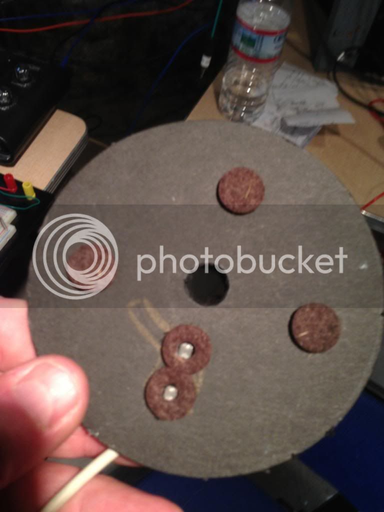
two disks, black. One for the mandrel (you can make more disks if you have more mandrels.
The felt rings help shield the light, and keep the lenses from getting scratched up.
It is precise to within 1 turn, but you can make it half turns or quarter turns if you want, but generally you have to stop on the same side of the bobbin anyway.
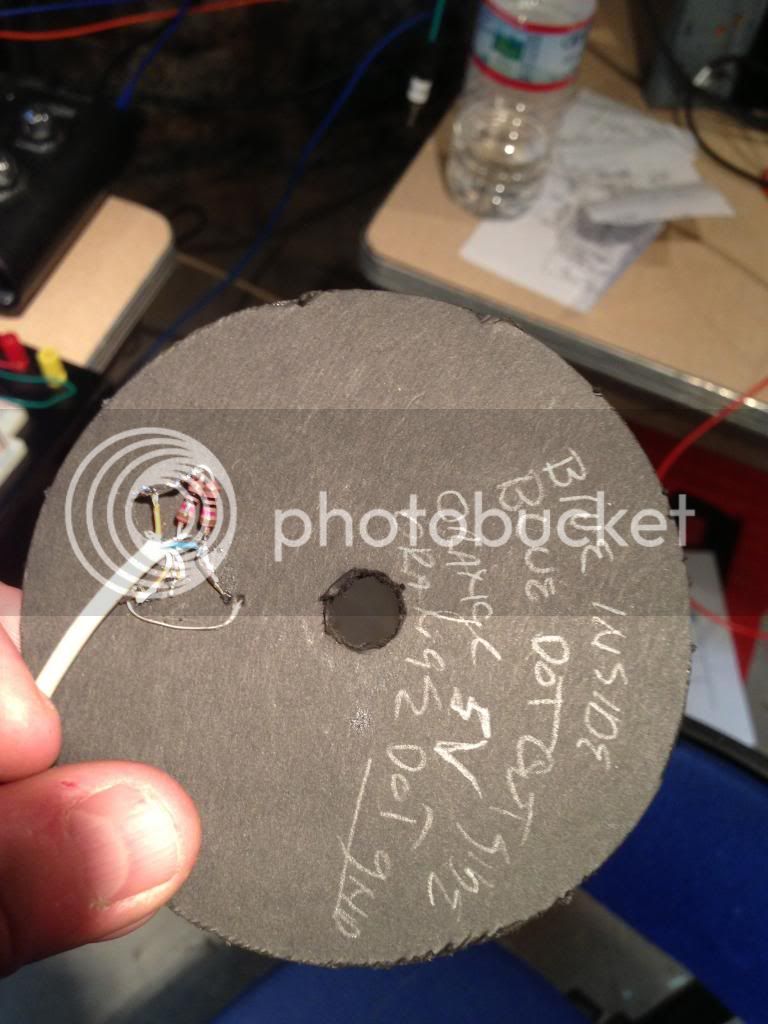
If it is not obvious, there are two LDR sensors placed radially on the other disk. If the outer one sees light first, the drill is going backwards, and visa versa.
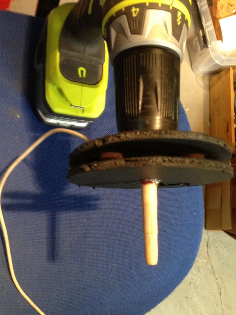
Disk is hot glued to mandrel, in this case tapered wood shaft for pot core bobbins.
How do you like those precision cuts!
Sunk the LDR's into the foam-core, punched two holes for the leads, and hot glued them in.
Punch a hole in the felt and give the LDR an eyelid (not sure it is needed, but I did it). The other felt pads are to prevent foamcore disks from touching.
That's the whole circuit. 5V off the arduino feeds two voltage dividers with 10K resistor connected to LDR and then ground. And the analog pins on the arduino fed by the junction of 10K and LDR. THis is an old piece of bell cable or something to keep it neat.
There is no attachment of the assembly to the drill (that is the great part of this design). It just hangs there. It worked fine with just the bell wire supporting it but I hot glued a wooden board on it for weight and to keep the two disks aligned better.
The whole assembly took me about 3 hours to put together and tweak and do two test windings (you have to tweek the "level" for the two LDR's which can be different). The test was winding two completely repeatable Pultec RM8 cores, within 2% of my target Henries. (wound 100 turns of reused magnet wire, measured core, adjusted the AL number in my spreadsheet then just wound based on counts, and it was right on). Second core was different AL, and they were next to each other on the packaging tape too.
I know this mount look loose, and that is what is so great about it. It is loose, and works perfectly for me. No tight tolerances, and no wiring to count backing up, it just does it based upon which LDR it sees first.
The arduino program is a hacked up version of one of the examples, it combines the edge detection example the analog read example and the debounce example... then I added a little bit.
I tried to make it calculate inductance on the fly but I didn't bother to download math libraries.
I think this could have a little LED display output, but that is a project for another day (and would bring the cost up to the cost of a totalizer which are 60 bucks or so).
IF you make one, when you set up you want to put the sensors on the side of the winder AWAY from you, so your fingers don't block the light and screw up the counts. But this is an easy, cheap way to count turns, and it gave me a change to learn a little about arduino.
I think you could hook this on most of the winders I see around on the site, and it would work. In my case the sensor is held in place by the mandrel and the disk with the slots in it. (there is no other attachement).
The code follows:
Tweaks are in variables and constancts, you might likely need to adjust them for your situation:
debounceDelay Prevents the sensor from toggling when it is near the light threshold. Don't want to count turns because a cloud or a kid rolls buy and the sensor is only part covered. (I use 5 milliseconds, if the LDR hits threashold for shorter than than then it doesn't count. You can shorten it it works at 3 depending on light. Since the slots cover about 10% of the arc of the circle, this limits counting to about 1000 RPM). Longer slots or a lower value here would increase that.
Don't bother changing pins, unless you have a reason. I left the digital pin version mostly intact (just commented out) THe LDR's use the analog pins.
// const int buttonPin = 12; // the pin that the pushbutton is attached to
const int sensorPin = A0; // the pin that the ldr is attached to
const int modeLeadPin = A1; // the pin that the ldr is attached to
// const int modePin = 8; // the pin that says forward or backward
Same threshold for both sensor..., 50 milliseconds. I tried higher but I think the LDR's have a "Dark Adaptation time" and mine was long, so you need to move it to the "operating range" for your LDR. Do this by experimentation. It is right when you spin the drill fast in both directions and it doesn't lose count. Two high...you will get missed and false counts depending upon lighting. Too low you will get missed counts.
const int sensorThreshold = 50;
/*
State change detection (edge detection)
Often, you don't need to know the state of a digital input all the time,
but you just need to know when the input changes from one state to another.
For example, you want to know when a button goes from OFF to ON. This is called
state change detection, or edge detection.
This example shows how to detect when a button or button changes from off to on
and on to off.
The circuit:
* pushbutton attached to pin 2 from +5V
* 10K resistor attached to pin 2 from ground
* LED attached from pin 13 to ground (or use the built-in LED on
most Arduino boards)
created 27 Sep 2005
modified 30 Aug 2011
by Tom Igoe
This example code is in the public domain.
http://arduino.cc/en/Tutorial/ButtonStateChange
*/
// this constant won't change:
// const int buttonPin = 12; // the pin that the pushbutton is attached to
const int sensorPin = A0; // the pin that the ldr is attached to
const int modeLeadPin = A1; // the pin that the ldr is attached to
// const int modePin = 8; // the pin that says forward or backward
const int ledPin = 13; // the pin that the LED is attached to
const long al = 3300; // in nanohenries
const int sensorThreshold = 50;
// Variables will change:
int buttonPushCounter = 0; // counter for the number of button presses
int buttonState = 0; // current state of the button
int modeState = 0; // current state of the forward/reverse mode
int lastModeState = 0; // previous state of the button
int lastButtonState = 0; // previous state of the button
int lastBounceState = 0; // previous momentary state
int lastModeBounceState = 0; // previous momentary state
int reading=0;
int mode=LOW;
// the following variables are long's because the time, measured in miliseconds,
// will quickly become a bigger number than can be stored in an int.
long lastDebounceTime = 0; // the last time the output pin was toggled
long debounceDelay = 5; // the debounce time; increase if the output flickers
long lastModeDebounceTime = 0; // the last time the output pin was toggled
long henries=0;
void setup() {
// initialize the button pin as a input:
pinMode(buttonPin, INPUT);
// initialize the button pin as a input:
pinMode(modePin, INPUT_PULLUP);
// initialize the LED as an output:
pinMode(ledPin, OUTPUT);
// initialize serial communication:
Serial.begin(9600);
}
void loop() {
// read the state of the switch into a local variable:
// int reading = digitalRead(buttonPin);
// read the input on analog pin 0:
int sensorValue = analogRead(A0);
int modeLeadValue = analogRead(modeLeadPin);
//debug
if (sensorValue > sensorThreshold ) {
reading=HIGH;
}
else {
reading=LOW;
}
if (modeLeadValue > sensorThreshold ) {
mode=HIGH;
}
else {
mode=LOW;
}
// check to see if you just pressed the button
// (i.e. the input went from LOW to HIGH), and you've waited
// long enough since the last press to ignore any noise:
// If the switch changed, due to noise or pressing:
if (reading != lastBounceState) {
// reset the debouncing timer
lastDebounceTime = millis();
}
if ((millis() - lastDebounceTime) > debounceDelay) {
// whatever the reading is at, it's been there for longer
// than the debounce delay, so take it as the actual current state:
buttonState = reading;
}
// If the mode changed, due to noise or pressing:
if (mode != lastModeBounceState) {
// reset the debouncing timer
lastModeDebounceTime = millis();
}
if ((millis() - lastModeDebounceTime) > debounceDelay) {
// whatever the reading is at, it's been there for longer
// than the debounce delay, so take it as the actual current state:
modeState = mode;
}
// compare the buttonState to its previous state
if (buttonState != lastButtonState) {
// reset the debouncing timer
// if the state has changed, increment the counter
if (buttonState == HIGH) {
// if the current state is HIGH then the button
// wend from off to on:
// if (digitalRead(modePin)==HIGH) {
if (modeState==HIGH) {
buttonPushCounter++;
}
else {
buttonPushCounter--;
}
// Serial.println("on");
henries=(buttonPushCounter*buttonPushCounter * al)/1000000;
//Serial.print("mH: ");
//Serial.println(henries,5);
//debug
//Serial.print(" switch: ");
//Serial.print(sensorValue);
// Serial.print(" mode: ");
// Serial.print(modeLeadValue);
Serial.print(" Turns: ");
Serial.println(buttonPushCounter);
}
else {
// if the current state is LOW then the button
// wend from on to off:
// Serial.println("off");
}
}
// save the current state as the last state,
//for next time through the loop
lastButtonState = buttonState;
lastModeState = buttonState;
// save the reading. Next time through the loop,
// it'll be the lastBounceState
lastBounceState = reading;
lastModeBounceState = mode;
// turns on the LED every four button pushes by
// checking the modulo of the button push counter.
// the modulo function gives you the remainder of
// the division of two numbers:
if (buttonPushCounter % 4 == 0) {
digitalWrite(ledPin, HIGH);
} else {
digitalWrite(ledPin, LOW);
}
}