DBX 118 problem...

GroupDIY Audio Forum

Help Support GroupDIY Audio Forum:

This site may earn a commission from merchant affiliate links, including eBay, Amazon, and others.

Golgoth

Well-known member
Joined
Jul 24, 2015
Messages
383
Location
Paris, France
Hello guys,

After months of research in every 118's thread on various forums, here I am.

I started with a faulty DBX 118 that had it's red light lit on all the time and no audio passing through.
So I replaced EVERY capacitors, EVERY opamps, the diodes, one resistor that looked strange on the RMS card and the 3046 transistor array also on the RMS.

Now I have a 118 that passes audio but the compressor side doesn't work, when I turn the knob to compress, the volume just go down. The red light also stays on all the time.

My guess is:
- Trimmers that moved? The glue seal is broken on the RMS card so I guess it has turned. Same thing on the VCA's, the trimmers move easily even if barely touched, they could have turned when I moved the 118 around...
- 3 pins transistors dead? I didn't replace them, VCA ones are BS453C, can't find them anywhere, RMS is K30R-A.
- Funny foil packages on the VCA's? Can't find what it is or any value for them.

Any help would be very much appreciated!
G.
 
If both channels behave identical, the problem isn't in VCAs. The foil packages are thermal coupled dual matched transistors. You should not mess with them.  The status RED LED always on indicates something faulty in RMS part and control circuitry, but it isn't so easy to find what's wrong without a scope.
 
Great thank you Amps,

What's your advice then? To change what I didn't replace on the RMS already?
By the way can I replace a K30A-R transistor by a K30A-GR or K30A-Y?
 
I can't suggest you anything specific, but you may check-replace usual suspects as tantal and electrolytic capacitors on the motherboard and RMS board. Did you check your power supply? Are +/-12V OK?
The R version of 2sk30 has lowest Idss. If you really need to replace it, use Y version, it is closer.
 
Hey  Moamps,

I already replaced every cap in the whole box (rms, vca's and board). I checked the power supply, +/-12V at every right spot.
My guess is RMS transistors + trimmer setting.

What do you think?

Thanks again for your help.
 
You may check it first. Apply signal at input and vary it's level. Check what's going on at outputs EO and CAP using a DMM where DC voltage should be in log relations with input's signal AC level.
Also, can you measure DC voltage on OA4 pins 5 and 7, and CAP output of the RMS module related to GND without signal applied?
 
Hi,

OA4 pin 5 reads 187mV DC, pin 7 is 0.6V DC without signal applied. Which one is the CAP output on the RMS?
I did apply a 400Hz signal for the other measurements but I don't really understand where to check exactly.
Sorry I'm a slow learner!

Thanks for your precious help!
 
EO is 3rd pin at P1 connecor or pin 5 of OA4.
CAP is 5th pin on P1 connector or -pin of capacitor C11.


Attachments

  • dbx118_rms.gif
    dbx118_rms.gif
    19.3 KB
EO = -237mV DC
CAP = - 0.69 V DC
Values are the same nevermind the signal level or frequency.

I measured without signal again:
OA4 pin 5 reads 100mV DC and is slowly rising up, pin 7 is -0.8V DC also slowly rising to 0.

I don't get "where DC voltage should be in log relations with input's signal AC level.". Should I measure something else or differently? I took all these measurements related to GND.

:(
 
Golgoth said:
EO = -237mV DC
CAP = - 0.69 V DC
Values are the same nevermind the signal level or frequency.

That's problem.
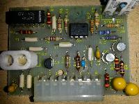
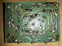
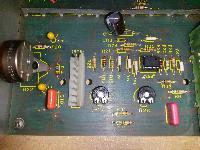
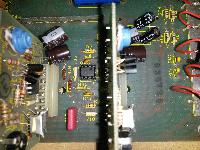
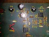
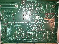
Could you post some pictures of  pcb and component side of RMS module and motherboard?
 
Please check the correct orientation of replaced tantal caps once again. I f everything looks ok,  you can check transistors on RMS module.
BTW, where are you located?
 
Hi,

Nothing changed with new transistors  :(

Could it be a short or cold solder joint somewhere? The RMS card looks pretty bad...
 
Here is schematic of rms module which isn't tested/checked.  Btw, there are few variants of vca/rms boards in 118.
 

Attachments

  • 1911086.jpg
    1911086.jpg
    39.4 KB
So, mine 128 is acting strange.  I believe I have it hooked up properly and that I have the proper buttons engaged to get some fun compression happening but, nothing really happening.

It passes audio, my threshold LED's bounce with the music and the LEVEL pot seems to act like a threshold should.  The thing that doesn't seem to be working is the compression/expansion pot.  It doesn't seem to do anything.    Here is my setup.

Signal into the inputs of the PLAY and out of the PLAY. 

NR set to PLAY, and the Dynamic Range Expander set to Pre.  In this position the Play Level match will work but no noticeable compression.

If I set the Dynamic Range Expander set to Post, I get no output.  Is that correct?

I have recapped all the tants and electolitcs.  I also swapped out the RC4558's and the TL082.  No difference.

When using my scope I don't see any signal on the inputs or outputs of the OA4 and OA5 IC's.  Seems like I should be seeing some signal there. 

Any help would be great. 
 
The topic is a little old, but maybe someone can answer me.

Does anyone know why in the PSU the ground is built with a voltage divider and buffered by a rc4558?

This limits a lot the max output current... Which by the way is unavailable in the datasheet of the rc4558...

Any clue? I'm tempted to substitute completely the PSU with an external one...
 
Back
Top