Deacy amp transformers

GroupDIY Audio Forum

Help Support GroupDIY Audio Forum:

This site may earn a commission from merchant affiliate links, including eBay, Amazon, and others.

rsasgtr

Member
Joined
Oct 28, 2021
Messages
21
Location
Spain
Hello everyone,

First time post here. I'm looking for suitable transformers for a Deacy-style amp. I would be very grateful for suggesting off-the-shelf ones or places to order custom-made ones. In the past I tried contacting multiple companies, but none were willing no make them. Knight Audio Technologies (deacyamp.com) used to have some, but they are obsolete now, and they won't make more in the future. I also consider winding them myself if I can obtain the parts, since they don't have many windings and are not high quality (see the story picture).

Based on the information I was able to gather:
The specs are (RDC 10% tolerance):
Interstage: 1500 turns (RDC 230 Ohm) : 275-0-275 (RDC 106 Ohm)
Output: 125-0-125 (RDC 8.6 Ohm) : 20-0-20 (RDC 4.3 Ohm)
Dimensions (mm): 25.4x21.3x19.9
Both dipped in varnish.

The speaker is 16 Ohm.

I don't know what the core type (someone suggested 262 laminations) is or what wire gauges are.

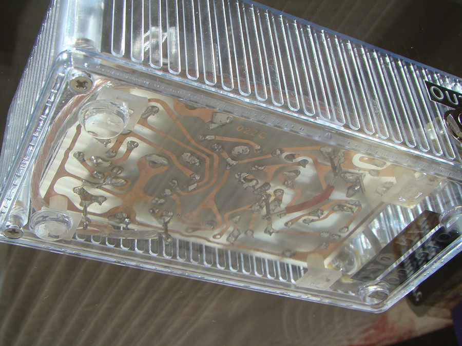
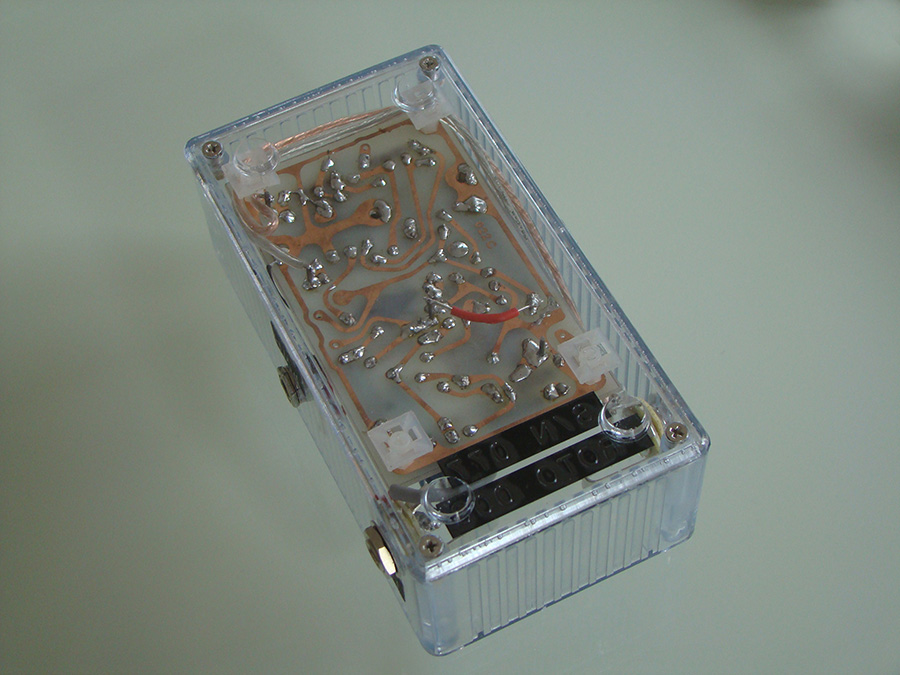
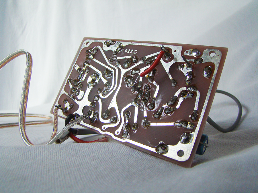
The Deacy amp schematic and some transformer pictures and story from deacyamp.com and other sources:

KAT Project 1 Watt Deacy-Style Amplifier Unit.png
transformers_on_pcb.jpg

Deacy Brochure20 copy.jpg
 
Actually the board in the deacy supposedly came from a Conquest PR80 transistor radio. There's a schematic of it on radiomuseum.org: Conquest PR80 (P.R. 80) but the guy is super anal about copyright so I won't post it here. You have to get an account and it has to be approved and you have to provide your IP and blah, blah, blah. It's super annoying.

But this pic from Hackaday which apparently came from some Mullard transistor manual (although NOT the Mullard Reference Manual for Transistor Circuits which I have and this circuit doesn't look like it's in there) does appear to be nearly identical to the PR80 circuit.

1636648801511.png

As you can see the OT is non-trivial. The speaker is actually connected to taps on the primary that also provide feedback to the bases and the secondary is providing feedback to the transistor driving the interstage transformer. So there are multiple feedback paths that probably tighten up the response and linearize things quite a bit. This is "hi-fi" for the early 60's.

I'm not sure what that KAT schematic is about. I have the PCB with KAT transformers that they used to sell as a kit and I don't think it matches that KAT circuit you posted. It might even be a bit of a rouse.

I hooked mine up and it sounded pretty rad. Of course if you want it to sound like Brian May, you'll probably have to have Brian May come over and play it for you.

Welcome to the list.
 
Hello Bo,
Actually the board in the deacy supposedly came from a Conquest PR80 transistor radio. There's a schematic of it on radiomuseum.org: Conquest PR80 (P.R. 80) but the guy is super anal about copyright so I won't post it here. You have to get an account and it has to be approved and you have to provide your IP and blah, blah, blah. It's super annoying.
I've got the PCB layout, schematics, from radiomuseum.org. Not soon enough to buy the kit from KAT though.
But this pic from Hackaday which apparently came from some Mullard transistor manual (although NOT the Mullard Reference Manual for Transistor Circuits which I have and this circuit doesn't look like it's in there) does appear to be nearly identical to the PR80 circuit.

View attachment 86186

As you can see the OT is non-trivial. The speaker is actually connected to taps on the primary that also provide feedback to the bases and the secondary is providing feedback to the transistor driving the interstage transformer. So there are multiple feedback paths that probably tighten up the response and linearize things quite a bit. This is "hi-fi" for the early 60's.

I'm not sure what that KAT schematic is about.
I'm familiar with the story. There's even more info on Greg Fryer's website: Deacy Amp
There is a person making clones based on the original radio circuits at DoxyWorld
Unfortunately, they don't sell transformers (I contacted them). But they do use off-the-shelf ones in their cheaper kit, so they do exist.

The image you posted comes from page 115 of the Supersonic Model PR 80 manual.
While the original transformer seems complicated, I'm trying to replicate the KAT version.
The original radio circuit was probably modified to make the amp, so maybe some taps where disconnected/changed, hence a simple KAT transformers.

I have the PCB with KAT transformers that they used to sell as a kit and I don't think it matches that KAT circuit you posted. It might even be a bit of a rouse.
I managed to get the PCB and the speaker. I was too late to the party.
The schematic comes from KAT's website. Did you get a different one with your kit?
Would you be able to willing to fill in the missing details, since you've got the transformers?
I hooked mine up and it sounded pretty rad. Of course if you want it to sound like Brian May, you'll probably have to have Brian May come over and play it for you.
I've got a modded start with Adeson Trisonic and a bunch of treble boosters. I can get close with amp sims. AC30 is too much for bedroom levels, but I'm still searching for the ultimate amp sim. AmpliTube is quite nice, but very noisy.
Welcome to the list.
Thanks!
 
As you can see the OT is non-trivial. The speaker is actually connected to taps on the primary that also provide feedback to the bases and the secondary is providing feedback to the transistor driving the interstage transformer. So there are multiple feedback paths that probably tighten up the response and linearize things quite a bit. This is "hi-fi" for the early 60's.
Expanding on the possible modifications it's clear in this picture that some taps of the output transformers are shorted.
Supersonic%20Doxy%207.jpg

Also the KAT circuit looks much more similar to PR80 when you flip the polarities. KAT uses positive ground, while the PR80 schematic seems to be using negative.
 
I sincerely doubt that the KAT schematic you posted is the one used in their reproductions. Notice how the schematic actually reads "Deacy-Style Amplifier". That circuit will not truely replicate the Deacy sound. Even a pignose model 7 has feeback from the speaker. You need the proper transformer and carefully selected germanium transistors (which is why the supply is positive ground). Unfortunately I don't think you're going to be able to do what you want with off-the-shelf parts.

Also, a Deacy amp is not a replacement for a regular practice amp. IIRC the signal is distorted more or less at all levels. It's really more of an effect. It's a 2nd harmonic generator.
 
I sincerely doubt that the KAT schematic you posted is the one used in their reproductions. Notice how the schematic actually reads "Deacy-Style Amplifier". That circuit will not truely replicate the Deacy sound. Even a pignose model 7 has feeback from the speaker.
You got me worried there, so I redraw the schematic from scratch from the PCB. I assume your PCB looks the same.
kat_pcb.png
kat_deacy.png
The only differences I noticed are:
1. The R8 resistor from the power supply goes before R6.
2. The order of R14 and C6 is reversed.
The transformer wiring seems to be the same.

Did you get the fully assembled amp from KAT, or did you assemble yours?

You need the proper transformer and carefully selected germanium transistors (which is why the supply is positive ground). Unfortunately I don't think you're going to be able to do what you want with off-the-shelf parts.
I agree. Would you be able to provide some details of the transformers from your kit?
 

Attachments

  • 1636664370967.png
    1636664370967.png
    232.5 KB · Views: 13
....I'm looking for suitable transformers for a Deacy-style amp...
If you take into account the information that can be found on this web site
https://yonderbosk.wordpress.com/the-deacish-amplifier-board/I would start with Hammond transformers.
145E or F for interstage and 146E, G or I for output. Each costs about 20Eur (Mouser).
After testing and determining the optimal winding ratios, I would maybe go looking for better quality transformers from other manufacturers.
 
You got me worried there, so I redraw the schematic from scratch from the PCB. I assume your PCB looks the same.
Yes. I just dug it out of the closet and my PCB is exactly the same. Unfortunately.
The only differences I noticed are:
1. The R8 resistor from the power supply goes before R6.
2. The order of R14 and C6 is reversed.
The transformer wiring seems to be the same.
The wiring is not at all the same. The PR80 circuit has taps for local transistor feedback. And the feedback from the speaker is to the interstage transformer transistor. The Deacy-Style circuit has feedback from the primary to the input transistor. The original PR80 circuit has no feedback to the first transistor which is fully bypassed. So the preamp is high gain and probably making a lot of second harmonic. Then the output has two feedback paths that are fairly linearized not unlike the presence control in a Fender Bassman or Marshall Plexi which, if you have every tried, tightens up the response a lot. When overdriven, feedback is defeated and so you could get very different results from these two circuits.

Unfortunately the kit that we both have is a Deacy-Style Amplifier and not the real-deal. I would be very surprised if the KAT replica units use the same board. Not based on what they went through to reverse everything.

It doesn't matter anyway. The tolerances on the various parts in that old PR80 circuit are wider than a truck. You have no idea what's going on in that original circuit. There could be a dozen different things going on from imbalance in the output transistors / transformer to supply sag from a dying battery.

Your time would be much better served just playing music and not chasing pixey dust from some amp that even the KAT replicas probably don't capture.
 
If you take into account the information that can be found on this web site
https://yonderbosk.wordpress.com/the-deacish-amplifier-board/I would start with Hammond transformers.
145E or F for interstage and 146E, G or I for output. Each costs about 20Eur (Mouser).
After testing and determining the optimal winding ratios, I would maybe go looking for better quality transformers from other manufacturers.
Thanks for the info. That PCB looks like a verbatim copy of the KAT circuit, so the Hammond transformers should at least work.
I tried looking up Hammond before, but they don't seems to provide the turns ratio, or I'm reading the spec incorrectly. E.g. here https://www.hammfg.com/electronics/transformers/audio/143-146.pdf How do you get the ratio from that spec?
 
The impedance ratio is the squared ratio of the turns ratio.
Eg. for 146E, the primary impedance is 100ohm, the secondary is 8 ohms.
The impedance ratio is 100/8 = 12.5, the turn ratio is 3.54.
 
The wiring is not at all the same.
I was replying to this:
I sincerely doubt that the KAT schematic you posted is the one used in their reproductions.
With the minor exception of the power supply resistor placement (which could be a mistake), the KAT schematic and their PCB are matching. But now I see what you meant (below).
Unfortunately the kit that we both have is a Deacy-Style Amplifier and not the real-deal. I would be very surprised if the KAT replica units use the same board. Not based on what they went through to reverse everything.
Now I see what you're saying. I was assuming that the PCBs and kits were just leftovers they were selling, but according to archive.org, they had been offering them way before they ran out of the replicas.
It doesn't matter anyway. The tolerances on the various parts in that old PR80 circuit are wider than a truck. You have no idea what's going on in that original circuit. There could be a dozen different things going on from imbalance in the output transistors / transformer to supply sag from a dying battery.
Given that I wonder how accurate the DoxyWorld replicas are, even if they use the same circuit. In their videos they sound very close.

How does your kit sound?
 
The impedance ratio is the squared ratio of the turns ratio.
Eg. for 146E, the primary impedance is 100ohm, the secondary is 8 ohms.
The impedance ratio is 100/8 = 12.5, the turn ratio is 3.54.
Thanks a lot. That cleared things up. One more question. When they provide centre-tapped impedance (I assume that's what e.g. 600 ct means), is it half of the whole value, i.e. impedance to the centre instead of end-to-end?
 
Unfortunately the kit that we both have is a Deacy-Style Amplifier and not the real-deal. I would be very surprised if the KAT replica units use the same board. Not based on what they went through to reverse everything.
To expand on my previous answer, I double checked the information I'd gathered, and the transformer specs I got from KAT are for their custom made transformers. Maybe they made 2 different sets (1 for the kit, 1 for the replica), or maybe they didn't.
Therefore, it would be very helpful if you could share some details on the transformers that you have. It's fine, if you are not willing to, but you haven't answered either way.
 
Given that I wonder how accurate the DoxyWorld replicas are, even if they use the same circuit. In their videos they sound very close.
The DoxyWorld replica looks legit. But it does look like it's wired a little differently from the PR80 schematic because from the pictures of the DoxyWorld PCB it looks like there's a bit of bus wire connecting one of the speaker terminals to ground and that cannot be if the center tap is connected to positive ground because that would be shorting out one of the windings. All the more reason why the PCBs we have are just not right.

This is not a DIY project. Either just buy a DoxyWorld unit and cross your fingers that it sounds good or move on.
 
But it does look like it's wired a little differently from the PR80 schematic because from the pictures of the DoxyWorld PCB it looks like there's a bit of bus wire connecting one of the speaker terminals to ground and that cannot be if the center tap is connected to positive ground because that would be shorting out one of the windings.
Only the version with off-the-shelf transformers, without the cabinet.
 
..When they provide centre-tapped impedance (I assume that's what e.g. 600 ct means), is it half of the whole value, i.e. impedance to the centre instead of end-to-end?
600ct means 600 ohms with center tap so it is impedance end to end.
 
How do you know that? Where is there a description of how the transformers are wired?
I looked at the pictures.
The PCB without the cabinet:
Supersonic%20Doxy%202.jpg

The PCB with the cabinet:
7.jpg

You can the extra connection close to the lower left corner is missing.
The description (https://doxyworld.com/images/documents/supersonic_doxy_spec.pdf) says the transformers are off the shelf.
I also found this schematic some time ago: https://uploads.tapatalk-cdn.com/files-2855/1541765610_gb_rgd_rr214_x_pcb1.pdf
It's from a different radio, but it's from the same 022C PCB.
 
You're right.

So the negative of the battery must not be connected to "ground". Because it's a battery, both + and - are floating. At least in the one without the cabinet it uses that one side of the speaker as "ground". And because the input is capacitor coupled, it still works. That was done so that the sleeves of the jacks are connected together like a typical guitar pedal.

So where are these "off-the-shelf transformers"?

The cabinet version specifications:

https://www.doxyworld.com/images/documents/supersonic_pro_spec.pdf
says the transformers are "hand-wound bespoke replicas of the original Supersonic transformers" which sounds like BS to me.

If the off-the-shelf ones have the right taps, that's not really going to be much different. If you can find those, that's 90% what you need to make one a legit one.
 

Latest posts

Back
Top