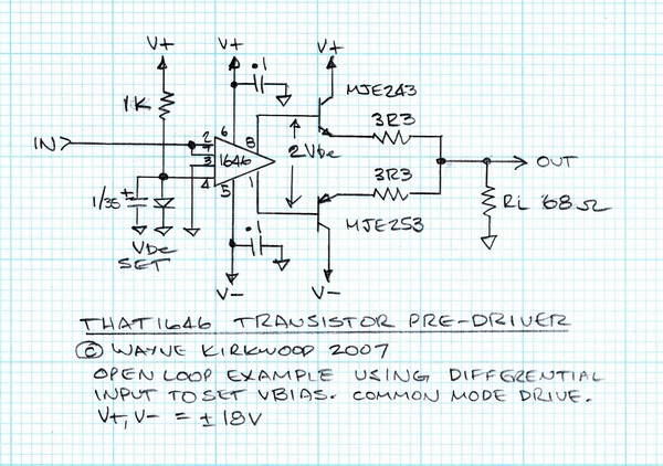
For Wavebourn et all.. my suggestion to add caps is not for the dynamic impedance of LEDs or large signal source impedance, the opamp loop gain will take care of all that, but to allow the bases of output devices to be driven above/below supply for some extra signal swing. Not a huge deal.
The last time I researched headphone amps, I found cans as low as 3.2 ohm, while not common, they were out there. I suspect part of the popular build out resistors on published headphone amp applications notes were to make those 3.2 ohms cans a little more manageable for cheesy IC drivers. The last headphone amp I made sounded OK with speakers too (TL07x opamp with some to-220 bipolars hung on the output), but I ended up power limiting the PS because driving speakers would take out the thermal fuse in the walwart PS after several minutes, if I didn't.
Regarding the popularity of using real amps on studio headphone distribution systems. IIRC it was also common to use couple hundred ohm build out resistors at each headphone jack so one low Z can wouldn't load down the whole string, and it would work with a wide range of brands/models, while not releasing their smoke.
JR
 ... ).