


Bo Deadly
Well-known member
I've been thinking about using a high voltage CMOS gate chip (ADG1414) to select inductor taps and capacitors in a resonant filter to make a EQ based on the following circuit:
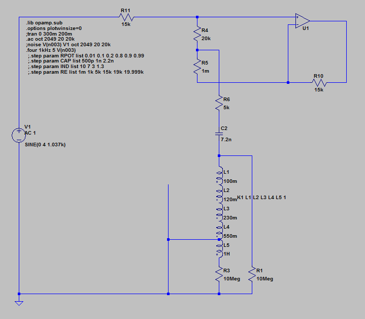
This is a very simple circuit. It's just like the API553 but CMOS gates would select the tap of an inductor like VTB9050 or similar and gates would also select some combination of capacitors and thereby make possibly many frequencies depending on the number of useful capacitor combinations.
The ADG1414 has pretty good specs to +- 15V. Distortion is low as long as the load is relatively high which in this circuit I think it should be 5k so it is.
However, there is one possibly fatal flaw. The voltage at the intersection of the inductor and capacitor can be quite high at the resonant frequency (let's call it the "flyback" voltage). At max boost, at the resonant frequency and with a high Q, the voltage can reach many times the supply (100V+). This is a deal-breaker because the protection diodes on the gates will just clip the signal at +-15V.
If I limit the boost to 12dB, and use resistor values as shown and limit the Q to 4, the flyback voltage is not too high and in theory the circuit should work fine.
So the question is:
is a Q of 4 too low for an eq
or is there a similar circuit to this one that would yield the same result but limit the "flyback" voltage effect
or is there a popular EQ circuit that can compete with the noise performance of an LC circuit and which can be reasonably constructed using conventional panel controls like DP12T Grayhill switches)?